In the modern construction landscape, precision is the difference between a project's success and a costly delay. Integrating Radio Frequency Identification (RFID) with Building Information Modeling (BIM) transforms static concrete into intelligent data points, providing unprecedented visibility into the lifecycle of precast components. This guide explores the technical bridge between physical assets and digital twins, offering a roadmap for contractors and BIM managers to automate workflows and eliminate manual errors on-site.
The Evolution of Precast Tracking: From Paper to Digital Twins

The evolution of precast tracking marks a critical transition from reactive, manual documentation to proactive, data-driven Digital Twins. Traditionally, the industry relied on paper manifests and physical markings, which were susceptible to human error and environmental degradation. Today, the integration of Radio Frequency Identification (RFID) technology into Building Information Modeling (BIM) software allows for a live, bidirectional flow of data. This ensures that every precast component—from casting and curing to shipping and installation—is accurately represented in a virtual model, providing a single source of truth that eliminates the 'data silos' common in large-scale construction projects.
| Feature | Manual/Paper | Barcode Systems | RFID + BIM Integration |
|---|---|---|---|
| Data Capture Speed | Slow (Manual Entry) | Moderate (Line-of-Sight) | Instant (Bulk Scanning) |
| Durability | Low (Lost/Damaged) | Moderate (Scanning Issues) | High (Embedded/Ruggedized) |
| Real-time Visibility | None (Post-hoc) | Low (Batch Sync) | High (Live Cloud Sync) |
| BIM Connectivity | None | Manual Linking | Automatic Object Updates |
While barcodes offered a bridge to digitalization, they failed to meet the unique demands of the precast yard. Concrete environments are harsh; dust, slurry, and stacking often obscure visual codes. RFID tags overcome these hurdles by utilizing electromagnetic fields to identify and track tags without requiring a direct line of sight. When these tags are linked to BIM, the physical component effectively becomes a 'smart object.' This synergy creates a Digital Twin, where the virtual model reflects the exact real-world status of the project in real-time.
Why did traditional barcodes fail in precast environments?
Barcodes require a clean line of sight and are easily damaged by concrete dust or abrasion during transport. In a crowded precast yard, scanning individual codes is labor-intensive compared to RFID, which can read hundreds of tags simultaneously through non-metallic obstructions.
What role does the Digital Twin play in component tracking?
A Digital Twin is a virtual replica of the physical jobsite. By integrating RFID data into BIM, project managers can see a color-coded 4D visualization of the site, identifying exactly which components are on-site, installed, or delayed without leaving the office.
Expert Insight: The 'Invisible Inventory' Tax. In my two decades of technical consulting, I've observed that companies using manual tracking lose approximately 15% of their operational efficiency simply searching for components in the yard. This 'invisible inventory tax' is the primary driver for RFID adoption. By embedding tags directly into the concrete during the casting phase, you aren't just tracking a part; you are creating a permanent digital birth certificate that remains accessible for the entire lifecycle of the building.
Selecting Hardware: Why Tag Durability Matters for Concrete

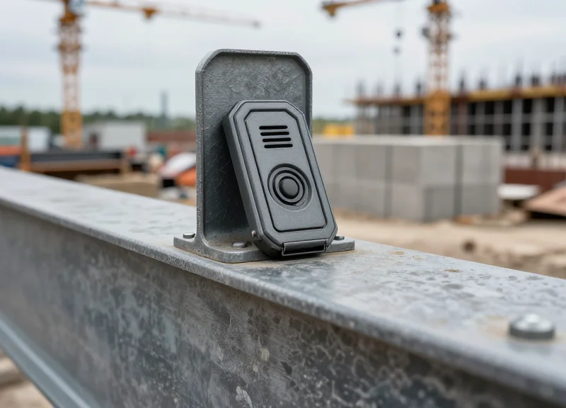
In the precast industry, an RFID tag is only as valuable as its ability to survive the 'Concrete Gauntlet'—a brutal cycle of high-heat hydration, chemical exposure, and mechanical vibration. Selecting hardware for precast tracking is not a matter of standard logistics; it requires ruggedized, passive UHF (Ultra-High Frequency) tags specifically engineered for embedding or surface-mounting on high-density materials. These tags must ensure the digital twin remains linked to the physical component from the casting bed to the final jobsite assembly, even after exposure to the elements.
| Environmental Stressor | Technical Requirement | Impact of Substandard Hardware |
|---|---|---|
| Exothermic Curing | Temperature resistance up to 85°C (185°F) | Internal circuit failure or melted encapsulation |
| Chemical Exposure | IP68 or IP69K rated (Chemical/Waterproof) | Corrosion of the antenna by alkaline concrete mix |
| Mechanical Vibration | High shock and vibration resistance | Micro-fractures in the IC-to-antenna bond |
| Signal Interference | Anti-metal/On-metal tuning | Zero read range due to rebar interference |
Expert Insight: The CTE Mismatch Risk. One critical, often-overlooked technical factor is the Coefficient of Thermal Expansion (CTE) of the tag’s encapsulation material. If the tag housing expands or contracts at a significantly different rate than the surrounding concrete during the exothermic curing phase, it can create micro-voids within the precast element. These voids do more than just weaken the structural bond; they allow moisture and chlorides to pool near the tag, eventually leading to signal attenuation or total hardware failure long before the component reaches the site.
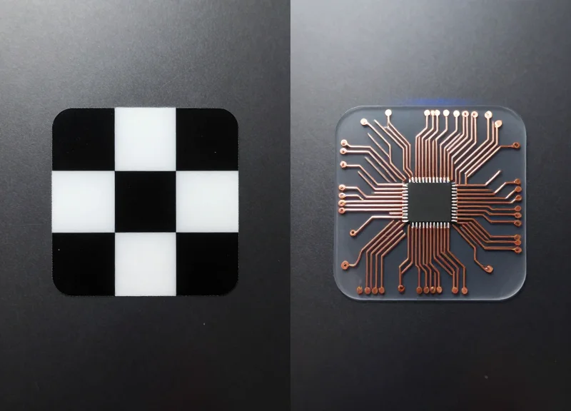
- Ceramic vs. PCB Tags: Ceramic tags offer high durability and small form factors but can be brittle. PCB-based tags with FR4 housing are generally preferred for precast for their balance of impact resistance and RF performance.
- Memory Capacity: Ensure the tag has at least 128 bits of EPC memory to hold unique identifiers that map directly to your BIM software (e.g., Revit or Tekla) GUIDs.
- Attachment Method: For embedded tags, use plastic zip-ties to secure the tag to the rebar cage. Avoid metal ties, which can cause 'detuning' and reduce the read range.
Can I use standard adhesive labels for precast tracking?
No. Standard labels will peel during hydration or be destroyed by the alkaline environment of wet concrete. Only use hard-encapsulated tags designed for industrial use.
Does the rebar cage block the RFID signal?
Yes, metal reflects RF energy. Tags must be placed as close to the surface as possible (within 10-20mm) and should be 'on-metal' tuned to leverage the rebar as a secondary reflector rather than a shield.
What is the typical read range for embedded concrete tags?
Expect a 30-50% reduction in read range once a tag is embedded in concrete compared to its open-air rating. High-quality concrete-optimized tags should still achieve 3-5 meters.
BIM Model Preparation: Creating Data Hooks for RFID

BIM model preparation for RFID tracking involves the creation of 'Data Hooks'—specific, standardized digital parameters within your modeling environment (such as Revit or Tekla) that act as the primary handshake between the physical precast component and its digital representation. These hooks are not merely text fields; they are structured data containers designed to store the Unique Identifier (UID) of an RFID tag, ensuring that every scan on the jobsite updates the correct object in the central model without manual mapping.
- Define the Shared Parameter Schema: Create a Shared Parameter file (.txt in Revit) to ensure that parameters like 'RFID_Tag_ID' and 'Production_Status' remain consistent across multiple project files and Revit families. This prevents data fragmentation when different subcontractors contribute to the model.
- Assign Parameters to Precast Categories: Map your new RFID parameters to the relevant IFC or BIM categories, such as Structural Framing, Structural Foundations, or Generic Models. This ensures that every precast beam, slab, or column automatically inherits the necessary tracking fields.
- Establish the Global Unique Identifier (GUID) Link: While the RFID tag has its own ID, you must map it to the software-generated GUID. This creates a secondary fail-safe; if a tag is damaged, the physical replacement can be re-linked to the model via the immutable GUID.
- Automate Data Entry with Scripts: Use Dynamo or Grasshopper to batch-populate the 'RFID_Status' field with a default value like 'Pre-Production' to ensure the database is ready for the first scan at the casting yard.
| Parameter Name | Data Type | Function | Source |
|---|---|---|---|
| RFID_UID | Text/String | Stores the hardware ID of the embedded tag. | RFID Scanner |
| Component_Status | Integer/List | Tracks progress (0=Casting, 1=Curing, 2=Shipped). | BIM Management App |
| Scan_Timestamp | Date/Time | Logs the exact moment of the last physical scan. | Mobile Gateway |
| Assembly_Position | Text | Reference to the installation grid/level. | BIM Model |
Expert Insight: The 'Ghost Parameter' Strategy. In large-scale precast projects, I recommend creating a hidden 'Sync_Lock' boolean parameter. When an RFID tag is scanned at the final installation point, this parameter toggles to 'True,' locking the geometry and location data in the BIM model. This prevents accidental coordination changes to components that are already physically bolted into the structure, effectively freezing the digital twin's 'as-built' state.
# Python snippet for Dynamo to batch-add RFID parameters to selected elements
import clr
clr.AddReference('RevitAPI')
from Autodesk.Revit.DB import *

doc = DocumentManager.Instance.CurrentDBDocument
elements = UnwrapElement(IN[0])
rfid_id = IN[1]

transaction = Transaction(doc, 'Assign RFID Tag')
transaction.Start()
for e in elements:
    param = e.LookupParameter('RFID_UID')
    if param:
        param.Set(rfid_id)
transaction.Commit()
Should I use Instance or Type parameters for RFID?
Always use Instance parameters. Each physical precast unit is unique and requires its own specific RFID UID, even if they share the same geometric Type.
What happens if a tag ID is entered twice?
Your BIM integration layer should include a validation script (or use a SQL 'Unique' constraint) to flag duplicate UIDs, preventing two physical beams from being mapped to the same digital object.
Can I track location through these hooks?
Yes, by adding a 'Last_Known_Location' parameter that stores GPS coordinates or zone IDs pushed from the RFID handheld reader during field scans.
Middleware Logic: Bridging the Gap Between Readers and Software

In the context of precast component tracking, middleware is the specialized software layer that intercepts raw, high-frequency signal data from RFID readers and translates it into structured, actionable updates for BIM platforms like Revit or Tekla Structures. This bridge is essential because hardware and BIM software speak fundamentally different languages; the middleware acts as a translator, filtering out duplicate reads, validating Electronic Product Codes (EPCs), and pushing the corrected data into the project's Common Data Environment (CDE). Without this logic layer, the digital twin would be overwhelmed by redundant data packets and 'ghost' signals from nearby tags.
- Signal Aggregation and Smoothing: Readers often ping a single tag hundreds of times per second. The middleware aggregates these bursts into a single 'Event,' reducing the load on the BIM server.
- Contextual Filtering: Logic filters ensure that only tags with the correct prefix (specific to the project) are processed, ignoring third-party tags or noise from nearby jobsite equipment.
- GUID Mapping: The middleware performs a lookup to match the unique RFID hex code to the BIM model's Global Unique Identifier (GUID), ensuring the physical beam and digital object are synced.
- Payload Transmission: Once validated, the data is packaged into a JSON or XML payload and sent via REST API to the BIM software's database.
| Data Phase | Format | Function |
|---|---|---|
| Ingestion | Raw EPC Hexadecimal | Capturing signal from hardware |
| Processing | Filtered Event Data | Removing duplicates and signal noise |
| Integration | API Post (JSON) | Updating BIM parameters (e.g., Status, Location) |
Expert Tip: To prevent the 'Ghost Read' phenomenon—where a reader accidentally picks up a tag on a passing truck 30 feet away—implement RSSI (Received Signal Strength Indicator) Thresholding. By setting the middleware to ignore any signal below a specific decibel-milliwatt (dBm) level, you ensure that only the component physically in front of the worker triggers a status change. This significantly increases the integrity of your site logistics data.
{ "rfid_tag_id": "E2801130200020B4", "bim_guid": "3b2e5a1a-0e9b-4f9e-a123-55664244aabc", "event_type": "StatusUpdate", "new_value": "Installed", "timestamp": "2023-11-01T14:30:00Z" }How does middleware handle offline site conditions?
Robust middleware uses 'Store-and-Forward' architecture. It caches timestamped scans locally on the reader or edge device and synchronizes them with the BIM model once an LTE or Wi-Fi connection is restored.
Can I use open-source middleware for BIM integration?
While frameworks like LLRP (Low Level Reader Protocol) exist, most precast firms opt for proprietary 'Edge Gateway' software provided by RFID vendors to ensure seamless API handshakes with construction management tools.
Implementation Workflow: From Fabrication to On-Site Installation

An effective RFID implementation workflow synchronizes physical material movement with a digital twin, ensuring that every precast element—from a bridge girder to a facade panel—is accounted for in real-time as it moves from fabrication to its final assembly on-site. By automating the data handshake between the manufacturing plant and the construction site, project teams can eliminate manual entry errors, reduce 'lost' components, and achieve 100% visibility into the supply chain status within the BIM environment.
- Pre-Pour Tagging and ID Mapping: Before the concrete is poured, passive RFID tags are secured to the reinforcement cage. The unique Electronic Product Code (EPC) is scanned and mapped to the specific GUID (Globally Unique Identifier) of the component within the BIM model. This creates the 'Digital Birth Certificate' for the element.
- Post-Cure Verification and Inventory Logging: Once the element is stripped from the mold and moved to the storage yard, a handheld or gate reader validates the signal. The status in the BIM software (e.g., Revit or Tekla) automatically updates from 'In Production' to 'Inventory/Cured'.
- Logistics Dispatch and Gate-Out: As components are loaded onto flatbeds, the driver’s manifest is digitally compared against the scanned RFID tags. This ensures the correct sequence of panels is shipped, preventing costly site delays caused by out-of-order deliveries.
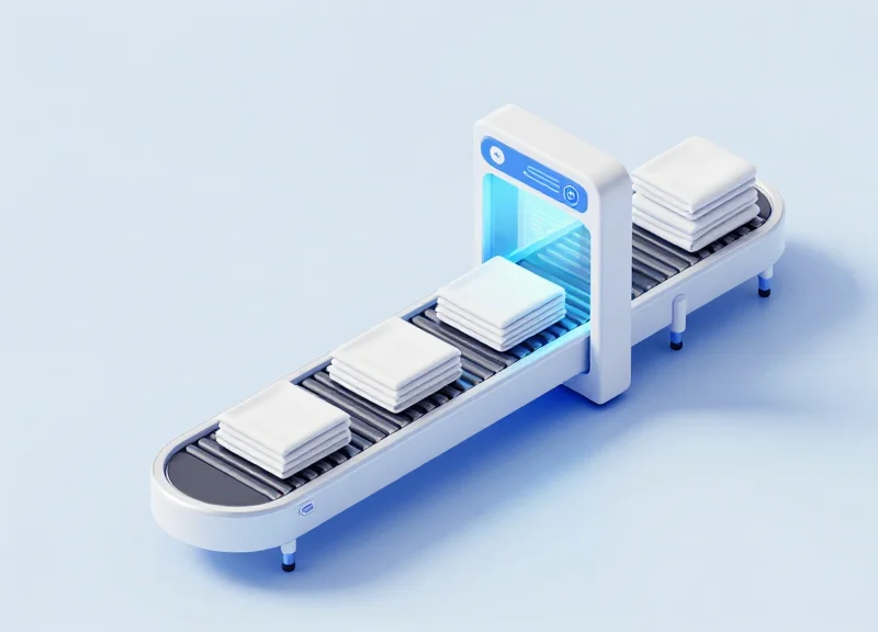
- Jobsite Arrival and Quality Acceptance: Upon arrival at the jobsite, a long-range portal reader captures the tags. The BIM model instantly changes the component color to 'On-Site,' alerting the crane crew and project managers that the piece is ready for installation.
- Final Placement and As-Built Status: After the component is hoisted and grouted into place, a final scan is performed. The middleware pushes a timestamp and coordinates to the BIM model, transitioning the status to 'As-Built' and triggering the automated billing cycle.
| Workflow Stage | RFID Action | BIM Status Update | Key Data Captured |
|---|---|---|---|
| Fabrication | Write/Embed Tag | In Production | Batch ID, Pour Date |
| Logistics | Gate Scan | In Transit | Truck ID, Departure Time |
| Arrival | Bulk Scan | On-Site Storage | Delivery Manifest Match |
| Installation | Final Proximity Scan | As-Built/Installed | Installation Timestamp |
Expert Tip: The 'Geometric Interlock' Verification. Most competitors focus only on tracking IDs. To truly differentiate your workflow, use the RFID scan to trigger a 'Geometric Interlock' check within your BIM middleware. By cross-referencing the RFID data with the crane’s GPS/telematics, the system can verify not just that the correct part is on-site, but that it is being placed in the correct spatial orientation. This prevents the nightmare scenario of installing a mirrored panel on the wrong side of a building, a mistake that often goes unnoticed until the next floor's assembly.
What happens if an RFID tag is damaged during transport?
Redundancy is key. High-reliability workflows utilize 'Twin-Tagging' (placing two tags on opposite ends of the component) or a secondary QR code backup that links to the same BIM GUID.
How does the site team access this data without a laptop?
The BIM-RFID integration typically pushes data to a mobile-friendly CDE (Common Data Environment) like Autodesk Construction Cloud or Procore, allowing foremen to view status updates via tablets.
Can RFID readers handle bulk scanning of multiple components on one truck?
Yes, UHF (Ultra-High Frequency) readers are designed for anti-collision, allowing them to read dozens of tags simultaneously as a truck passes through a site gate at low speed.
Real-Time Data Synchronization and Cloud Integration

Real-time data synchronization in RFID-enabled BIM workflows is the automated process of updating a centralized cloud-based model with field-captured status updates without manual data entry. By utilizing mobile RFID readers connected to cellular or mesh networks, site personnel can transmit 'Proof of Delivery' or 'Installation Complete' timestamps directly to the Common Data Environment (CDE). This ensures that project managers in the field office see an identical 'As-Built' status as the crew on the jobsite, eliminating the lag time that typically plagues complex precast concrete logistics.
| Feature | Legacy Manual Reporting | Real-Time RFID Cloud Sync |
|---|---|---|
| Data Latency | 24-48 hours | Sub-second to 5 minutes |
| Accuracy | High human error risk | 99.9% automated verification |
| Source of Truth | Spreadsheets / Paper logs | Centralized BIM Model (CDE) |
| Visibility | Reactive decision making | Proactive bottleneck detection |
To achieve a seamless flow, the integration must account for the reality of construction sites: intermittent connectivity. An 'Offline-First' mobile architecture is essential, where the reader caches scans locally and synchronizes with the cloud once a stable connection is re-established. This prevents data loss during basement installations or in remote areas with poor LTE/5G coverage.
- Field Capture: A ruggedized mobile RFID reader or a smartphone with a bolt-on UHF reader scans the precast component tag, capturing its unique EPC (Electronic Product Code).
- Edge Processing: The mobile application appends metadata such as GPS coordinates, timestamp, and the operator's ID to the scan event.
- API Transmission: The data is pushed via a RESTful API or GraphQL mutation to the cloud middleware, which serves as the traffic controller between hardware and software.
- BIM Model Update: The middleware interacts with the BIM platform's API (e.g., Autodesk Construction Cloud API) to update the specific component's status parameter from 'In Transit' to 'On Site'.
Expert Insight: For large-scale projects, adopt a 'Delta-Sync' strategy. Instead of refreshing the entire BIM model for every scan, only synchronize the changed parameters (the 'deltas'). This drastically reduces bandwidth consumption and prevents UI lag in the BIM viewer, allowing the model to stay responsive even with thousands of concurrent field updates.
How do we handle data collisions if two workers scan the same tag?
Implement a 'Last-In-Wins' logic or a versioning timestamp at the middleware level to ensure the most recent chronological scan takes precedence.
What cloud platforms are best for RFID-BIM integration?
Autodesk Construction Cloud (formerly BIM 360) and Procore are the industry leaders due to their robust open APIs and established developer ecosystems.
Can we trigger automated alerts based on these scans?
Yes, by integrating Webhooks, you can trigger automated emails or Slack notifications to the procurement team the moment a critical-path component arrives on site.
Overcoming Signal Interference in Steel-Reinforced Concrete
To overcome signal interference in steel-reinforced concrete, engineers must utilize Ultra-High Frequency (UHF) passive RFID tags specifically designed for 'on-metal' applications, positioned at a minimum offset of 20mm from internal rebar grids. This strategic spacing prevents the Faraday cage effect—where the dense steel mesh absorbs or reflects radio frequency (RF) energy—allowing the signal to propagate through the concrete's dielectric medium to the reader.
In precast construction, the primary challenge is the physics of the environment. Steel is a conductor that causes detuning and signal reflection, while concrete, particularly when wet or 'green,' has a high dielectric constant that can attenuate UHF signals. Managing these variables requires a combination of specialized hardware and precise spatial installation within the BIM model's coordination phase.
| Tag Type | Frequency Range | Steel Interference Resistance | Best Use Case |
|---|---|---|---|
| Standard Wet Inlay | UHF (860-960 MHz) | Very Low | Non-reinforced items or packaging |
| Ceramic On-Metal Tag | UHF (860-960 MHz) | High | Surface mounting on finished concrete |
| Encapsulated PCB Tag | UHF (860-960 MHz) | Very High | Deep embedding near heavy rebar cages |
| Active RFID (Battery) | 2.4 GHz / 433 MHz | Moderate | Long-range yard tracking only |
- Map Rebar Density in BIM: Before physical casting, use your BIM software to identify 'RF Windows'—areas where rebar spacing is widest—to serve as the primary host location for the RFID tag.
- Utilize Non-Conductive Spacers: Secure the RFID tag to a plastic chair or specialized non-conductive spacer. Ensuring the tag is not in direct contact with the steel prevents the tag’s antenna from being 'shorted' by the reinforcement.
- Optimize Antenna Orientation: Align the tag's polarization (linear or circular) with the expected path of the reader. For precast walls, vertical orientation usually yields the best backscatter signal when scanned from ground level.
Expert Insight: The 'Concrete Lens' Effect. While we often view concrete as a barrier, dry cured concrete actually acts as a dielectric resonator. By positioning a UHF tag approximately 25mm to 40mm below the surface (the 'sweet spot'), you can actually leverage the concrete's properties to focus the RF energy, sometimes resulting in a more stable read range than a tag placed on the surface where it is prone to multipath interference from surrounding site equipment.
Does wet concrete block RFID signals entirely?
Not entirely, but moisture significantly increases signal absorption. It is recommended to perform final QA/QC scans once the precast unit has reached at least 70% of its design strength, as water content will have sufficiently dissipated.
Can I use HF (High Frequency) tags instead?
HF tags (13.56 MHz) are less affected by moisture but have a very short read range (usually <10cm). For industrial jobsite tracking where components are stacked or on trailers, UHF is the only viable standard for bulk reading.
How do I handle double-reinforced mats?
In double-mat configurations, tags should always be placed on the outer face of the reinforcement closest to the exterior concrete surface. Never place a passive tag between two dense layers of steel mesh, as this creates a near-perfect RF shield.
Analyzing ROI: Efficiency Gains and Error Reduction
Return on Investment (ROI) for RFID-BIM integration is primarily driven by the elimination of 'information latency'—the time gap between a physical site event and its reflection in the digital model. While traditional manual tracking leads to a 5-10% discrepancy in inventory data, an integrated RFID system ensures 99.9% data accuracy, enabling project managers to make decisions based on real-time field realities rather than outdated spreadsheets. By automating the data capture process, firms typically see a total project cost reduction of 3% to 5% through optimized logistics and reduced material waste.
| Key Performance Indicator | Manual/Barcode Workflow | Integrated RFID-BIM Workflow |
|---|---|---|
| Inventory Audit Speed | 4-8 Hours per Site Walk | 15-30 Minutes via Handheld/Gate |
| Data Entry Error Rate | 5% - 12% (Human Error) | < 0.1% (Automated Capture) |
| Component Locate Time | 20-40 Minutes per Unit | < 2 Minutes via Proximity Search |
| Rework due to Wrong Part | High Risk (Visual Verification) | Near Zero (Software Validated) |
Beyond simple time savings, the integration mitigates the 'Latent Data Tax'—the hidden costs associated with searching for lost components or correcting mismanaged sequencing. When the BIM software automatically flags that a 'Level 4' panel has arrived at the site while the schedule is still on 'Level 2', it prevents logistical bottlenecks before they manifest as costly crane downtime.
- Labor Optimization: Field engineers spend up to 40% of their time documenting progress; RFID automation reallocates this high-value labor to quality control and safety management.
- Supply Chain Transparency: Real-time visibility into the fabrication and transit status allows for 'Just-In-Time' delivery, reducing site congestion and double-handling of heavy precast units.
- Claims and Dispute Mitigation: The immutable digital trail of when a component was cast, shipped, and installed serves as a definitive 'single source of truth' for insurance and contractual disputes.
Expert Insight: The Digital Legacy Premium. A often overlooked ROI factor is the increased value of the 'As-Built' model. By embedding RFID tags permanently within precast concrete, you provide the building owner with a 'Digital Twin' that remains functional for the building's entire lifecycle. This facilitates non-destructive testing and maintenance decades later, as facility managers can scan a wall and instantly retrieve its reinforcement details from the original BIM file. This long-term data utility can be a decisive competitive advantage during the bidding phase.
How long is the typical payback period for RFID-BIM hardware?
Most mid-to-large scale precast projects achieve a break-even point within 12 to 18 months, primarily through the reduction of labor hours and the elimination of one or two major rework incidents.
Does the cost of tags outweigh the benefits for smaller projects?
While the initial overhead for readers is fixed, the per-tag cost for UHF RFID is now low enough that even on smaller projects, the prevention of just one incorrectly installed structural unit covers the cost of tagging the entire project.
What is the primary driver of ROI in facility management?
The ability to perform 'blind' maintenance—locating embedded utility junctions or structural connections without invasive drilling—saves owners thousands in inspection and repair costs over the asset lifecycle.