The tobacco industry is rapidly adopting RFID technology to enhance supply chain traceability and combat counterfeiting. However, the high-speed, metal-dense environment of tobacco packaging machines presents a significant challenge: signal interference. When RFID readers are integrated into these complex systems, electromagnetic reflections from metal surfaces can lead to read errors and decreased efficiency. This guide provides an authoritative roadmap for optimizing on-metal tagging and achieving seamless RFID integration without compromising signal integrity.
The Physics of Interference: Why Metal is a Challenge for RFID

RFID technology struggles with metal surfaces because metallic environments create two primary physical barriers: electromagnetic reflection and the induction of eddy currents. When an RFID reader emits radio frequency (RF) energy toward a metal object, the metal acts as a mirror, reflecting the waves and causing multi-path interference. Simultaneously, the magnetic field induces eddy currents on the metal surface, which generate an opposing magnetic field that effectively 'shorts out' the tag’s antenna. This phenomenon, known as detuning, shifts the tag's resonant frequency away from the reader's operating frequency, rendering the tag invisible to the system.
| Interaction Factor | Non-Metallic Surface (Plastic/Cardboard) | Metallic Surface (Steel/Aluminum) |
|---|---|---|
| RF Wave Behavior | Transmission/Absorption | Reflection (Multi-path) |
| Magnetic Field | Unimpeded Pass-through | Opposing Eddy Currents |
| Tag Resonant Frequency | Remains Stable | Significant Detuning/Shift |
| Required Tag Type | Standard Inlay | On-Metal (MOM) / Spaced Tag |
In tobacco packaging machines, the challenge is amplified. These machines are massive assemblies of steel and aluminum, often operating at high speeds. When a standard RFID tag is placed directly on a metal chassis or near foil-lined cigarette packs, the 'near-field' coupling is disrupted. The tag's antenna inductance changes, which causes the energy transfer between the reader and the chip to fail. Without a dielectric spacer to create a physical gap, the signal is literally grounded by the metal’s conductivity.
What is the 'Faraday Cage' effect in tobacco packaging?
This occurs when metallic components or foil-lined packaging surround the RFID tag, creating an enclosure that blocks all external RF signals from reaching the tag's antenna.
Why does frequency matter for on-metal applications?
Ultra-High Frequency (UHF) RFID is particularly sensitive to metal because its shorter wavelengths are easily reflected, creating 'null zones' where the signal cancels itself out.
Expert Insight: In the tobacco industry, the 'Foil Factor' is often overlooked. Standard metallic-foil inner liners in cigarette packs act as a parasitic capacitance source. Even if your RFID reader is professionally mounted to the machine frame, the proximity of the foil-lined product itself can shift the tag's tuning by as much as 20-30 MHz. To mitigate this, engineers must select tags specifically pre-tuned for high-permittivity environments rather than generic industrial on-metal tags.
Selecting Specialized On-Metal RFID Tags for Tobacco Packaging

Selecting specialized on-metal RFID tags for tobacco packaging requires moving beyond standard passive inlays to tags engineered with a dielectric spacer or ceramic substrate. Unlike standard tags that fail when applied to conductive surfaces, specialized on-metal (MOM) tags are designed to utilize the metal surface as a functional ground plane. This design prevents the 'short-circuiting' of the tag's antenna and ensures that the electromagnetic field remains accessible to the reader even when the tag is mounted directly onto foil-lined cartons, aluminum tins, or stainless steel machinery parts.
| Tag Type | Construction | Best Use Case | Durability |
|---|---|---|---|
| Flexible On-Metal | Thin foam/PET spacer | Foil-lined soft packs and curved surfaces | Moderate |
| PCB / FR4 Tags | Glass-reinforced epoxy | Permanent machine part tracking | High |
| Ceramic Tags | Hard ceramic substrate | Small-scale tins or high-heat environments | Extreme |
| Flag Tags | Standard inlay with fold | Protruding from metallic edges | Low |
In the tobacco industry, space is often at a premium. Tobacco packaging machines operate at incredibly high speeds (up to 1,000 packs per minute), meaning the tag must not only be readable but also physically unobtrusive to avoid jams. While a thicker foam spacer provides a better read range by increasing the distance from the metal, it also increases the risk of the tag being stripped off by mechanical guides. Therefore, PCB-based tags are often preferred for internal machine components due to their low profile and high impact resistance, while flexible on-metal tags are the standard for secondary packaging like metallic finished cartons.
- The 'Shadow Zone' Insight: A common mistake in tobacco line integration is over-speccing the read range. In high-speed packaging, a tag with too much gain can cause 'cross-talk,' where the reader picks up a tag three stations away instead of the one directly in front of it. An expert tip is to select tags with a 'controlled' read range of 30-50cm, which ensures the reader only sees the intended pack within its specific 'data window' on the conveyor.
- Adhesive Shear Strength: Tobacco dust is fine and abrasive. When selecting tags, ensure the adhesive is rated for high shear strength and low surface energy (LSE) plastics or metals to prevent 'tag creep' caused by the constant vibration of the packaging line.
Can I use a standard RFID tag with a DIY spacer?
While technically possible, DIY spacers are unreliable for high-speed tobacco lines. Factory-tuned on-metal tags have their antennas specifically calibrated for the dielectric constant of the spacer material, ensuring consistent resonance that a manual spacer cannot guarantee.
How does moisture in tobacco affect tag selection?
Tobacco is hygroscopic. While the metal packaging is the primary concern, high moisture content can further detune the signal. Using an IP68-rated PCB tag ensures that moisture does not seep into the tag's IC bonding, maintaining signal integrity over time.
Are there tags small enough for individual cigarette tins?
Yes, ceramic UHF tags as small as 3x3mm are available. These are ideal for luxury metal tins, providing a discreet but robust tracking solution that survives the supply chain without affecting the aesthetic of the premium packaging.
Strategic Antenna Placement: Avoiding Null Zones

Strategic antenna placement is the practice of positioning RFID readers within the machine's architecture to minimize 'null zones'—areas where reflected radio waves cancel each other out, resulting in a zero-signal environment. In tobacco packaging, where aluminum foil liners and stainless steel conveyor parts are ubiquitous, avoiding these zones requires a precise calculation of wave polarization and the 'standoff distance' from metallic backplanes to ensure consistent tag readability during high-speed operation.
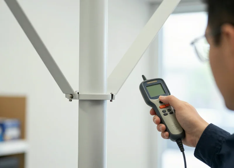
- RF Field Mapping: Conduct a site survey using a signal strength indicator (RSSI) to identify areas of destructive interference. Map the machine's workflow to ensure the tag passes through the 'sweet spot' of the antenna's main lobe.
- Polarization Alignment: Match the antenna's polarization (circular vs. linear) with the orientation of the on-metal tags. Circular polarization is generally preferred in packaging to capture tags at varying angles as boxes move through the folder.
- Angular Offsetting: Avoid mounting antennas perfectly parallel to large metal surfaces. Tilting the antenna by 5 to 15 degrees can deflect reflected waves away from the receiver, reducing multipath interference.
- Parabolic Clearance: Maintain a clearance zone around the antenna's face. Placing an antenna too close to a metal pillar creates a 'near-field' loading effect that can detune the antenna itself.
| Antenna Type | Recommended Standoff | Optimal Use Case | Interference Risk |
|---|---|---|---|
| Circular Polarized | 15-30 cm | Variable tag orientation | Moderate multipath |
| Linear Polarized | 30-60 cm | Fixed, high-speed lines | High if misaligned |
| Near-Field Patch | 0-5 cm | Item-level foil tracking | Very Low |
Expert Insight: In the tobacco industry, the 'Vibration-Phase' effect is often overlooked. Because packaging machines vibrate at specific frequencies, the physical distance between the antenna and a metal reflector can fluctuate by millimeters. At UHF frequencies (860-960 MHz), a shift of just 8cm can move a tag from a peak signal to a total null. To counter this, we recommend using 'Diversity Switching'—deploying two antennas with a 1/4 wavelength offset to ensure that when one is in a null, the other is at peak gain.
Can I use metal shielding to improve signal?
Yes, strategic shielding behind the antenna can focus the beam forward and block noise from adjacent motors, but it must be placed at a distance that avoids detuning the antenna's impedance.
What is the best height for the antenna?
The antenna should be centered on the vertical axis of the tag's path, typically 10-20% above the conveyor belt to account for the reflective properties of the belt itself.
How do I handle aluminum foil packaging?
Foil acts as a mirror. Use a cross-polarized antenna setup to capture the signal even when the foil causes a phase reversal in the reflected wave.
Managing RF Reflection with Shielding and Absorbers
In the high-speed environment of tobacco packaging, RF reflection—often called 'multipath interference'—occurs when radio waves bounce off metallic machine frames, foil linings, and conveyors, causing ghost reads or signal nulls. Effective management involves using RF-absorbing materials (like ferrite-filled elastomers) to soak up stray energy and conductive shielding to physically isolate the interrogation zone. By transforming a chaotic metallic environment into a controlled 'RF tunnel,' engineers can ensure that the reader communicates only with the intended tag on the specific package passing through the gate.
| Material Type | Primary Function | Best Used For | Typical Thickness |
|---|---|---|---|
| Ferrite Absorbers | Energy Dissipation (Heat) | Eliminating near-field reflections on metal frames | 0.1mm - 2.0mm |
| Carbon-Loaded Foam | Broadband Absorption | Lining large enclosures to prevent signal leakage | 5mm - 25mm |
| Conductive Foil/Mesh | Signal Reflection/Blocking | Creating a Faraday cage effect around the read zone | 0.05mm - 0.5mm |
| Hybrid Absorbers | Dual-Band Mitigation | Complex environments with both HF and UHF interference | 1.0mm - 3.0mm |
Expert Tip: The 'Faraday Funnel' Strategy. Instead of trying to shield the entire machine, Silicon Valley engineers often employ a 'funnel' approach. By placing high-permeability ferrite sheets directly behind the RFID antenna and lining the entrance/exit points of the read station with microwave absorbers, you create a directional path that 'pulls' the RF field toward the product while deadening the energy that would otherwise bounce off the metallic conveyor rails. This significantly improves the signal-to-noise ratio (SNR) and allows for higher line speeds.
- Identify RF Hotspots: Use a handheld spectrum analyzer or RSSI (Received Signal Strength Indicator) heat mapping to find areas where signal bounce is highest, typically around corners or large metal plates.
- Select the Correct Frequency Rating: Ensure absorbers are tuned to the specific 860-960 MHz (UHF) or 13.56 MHz (HF) range used in your tobacco tracking system; generic foam often fails at these specific industrial bands.
- Apply Peel-and-Stick Ferrite: Apply flexible ferrite sheets to the metallic surfaces closest to the antenna to prevent the 'detuning' of the antenna’s own radiation pattern.
- Validate with Stress Testing: Run the packaging line at full speed with a mix of empty and full tobacco packs to ensure the shielding doesn't create new 'blind spots' as the mechanical configuration shifts.
Will RF absorbers degrade over time in a tobacco plant?
High-quality silicone-based or ferrite absorbers are highly resistant to the dust and heat typical of tobacco processing, though they should be wiped down periodically to prevent particulate buildup from altering the dielectric properties.
Can I just use aluminum foil for shielding?
While aluminum foil blocks signals, it also reflects them. In tight spaces, this can actually worsen multipath interference. Absorbers are generally preferred over simple shielding for internal machine components.
How much does shielding impact read range?
Proper shielding might reduce total raw range but significantly increases 'read accuracy.' By limiting the field to 30-50cm, you prevent the reader from accidentally triggering tags on adjacent pallets or conveyors.
Synchronizing Readers with PLC Systems for High-Speed Lines

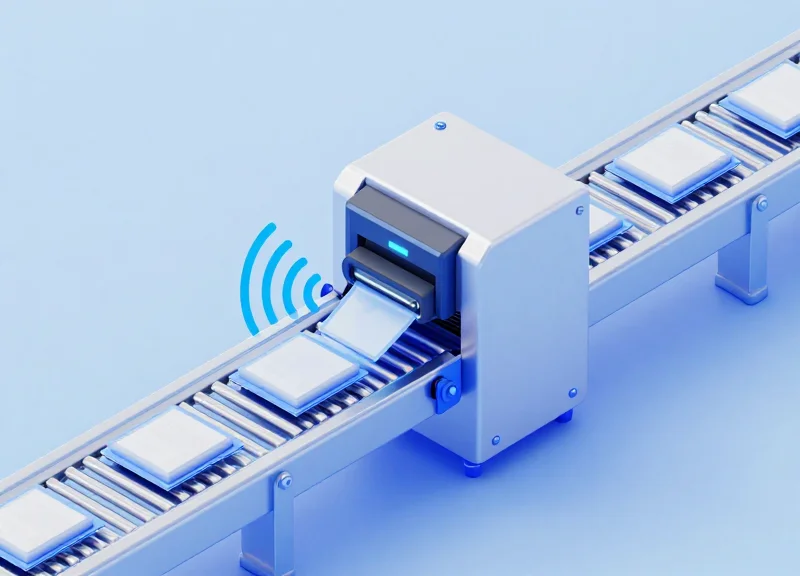
Synchronization in high-speed tobacco packaging is the process of aligning the RFID reader's interrogation window with the Programmable Logic Controller (PLC) scan cycles to ensure that every unique tag is captured and verified within a millisecond-level window. In environments where lines move at 600 to 1,000 packs per minute, relying on autonomous reading (continuous mode) often leads to 'buffer overflow' or duplicate reads; instead, successful integration utilizes a 'Triggered Gating' approach, where the PLC tells the reader exactly when to energize based on physical sensor inputs or encoder positions.
- Select a Deterministic Protocol: Choose communication protocols like PROFINET or EtherNet/IP that support real-time data exchange. These allow the PLC to prioritize RFID data packets over standard network traffic.
- Implement Hardware Triggering: Wire a photo-eye or proximity sensor directly to the RFID reader's GPIO input port. This bypasses network latency, initiating the read cycle the instant a package enters the RF field.
- Configure the Heartbeat Mechanism: Establish a 'heartbeat' signal between the PLC and the reader to monitor connection health. If the reader lags or fails to respond within a set millisecond threshold, the PLC can trigger an immediate line stop or divert the package.
- Data Buffering and Handshaking: Use a 'New Data Ready' bit in the PLC logic. The reader populates a data register, flips the bit, and the PLC acknowledges receipt before the next package arrives.
| Protocol | Typical Latency | Best Use Case | Reliability Level |
|---|---|---|---|
| PROFINET (IRT) | < 1 ms | High-speed Siemens-based lines | Critical/Ultra-High |
| EtherNet/IP | 2 - 10 ms | Standard Allen-Bradley integrations | High |
| Modbus TCP | 10 - 50 ms | Legacy systems / Low-speed monitoring | Moderate |
| RS-232/Serial | Varies | Point-to-point specialized sensors | Low (Electrical Noise Risk) |
Expert Insight: The 'Buffer Mirage' is a common pitfall in high-speed RFID implementation. Many engineers assume that if the reader's internal memory shows a successful read, the system is working. However, at high speeds, the bottleneck is often the PLC's 'Scan Time'. If your PLC scan time is 15ms but packs are passing every 10ms, you will lose data. To solve this, utilize a 'First-In-First-Out' (FIFO) stack within the RFID controller itself to buffer tag IDs, allowing the PLC to drain the queue at its own maximum processing speed without missing a single serial number.
What happens if two tags are read at once?
This indicates a 'bleed' issue from the previous or next package. Use RSSI (Received Signal Strength Indicator) filtering in the PLC logic to ignore any signal weaker than the primary package currently in front of the sensor.
Should I use a software trigger or a hardware trigger?
Always prioritize hardware triggers (GPIO) for high-speed lines. Software triggers sent over the industrial network are subject to jitter and stack delays which can cause the read window to open too late.
How do I handle read errors without stopping the line?
Implement a 'Shift Register' in the PLC. Assign a 'Null' value to the failed read and track that specific package position until it reaches a pneumatic reject station further down the line.
Software Optimization: Filtering and Signal Strength Tuning
Software optimization is the process of fine-tuning a reader's internal logic to distinguish between the 'target tag' and 'noise' or 'leakage' from adjacent packaging units. In the reflective, metal-heavy environment of a tobacco packaging machine, this involves setting strict Received Signal Strength Indicator (RSSI) floors and dynamically adjusting transmit power. By defining a software-based 'digital perimeter,' engineers can ensure that even if RF energy spills over into a neighboring conveyor lane, the reader ignores those signals because they do not meet the minimum power or persistence requirements established during the tuning phase.
| Parameter | Setting Level | Impact on Performance | Risk Factor |
|---|---|---|---|
| Transmit Power | Low (15-20 dBm) | Reduced signal leakage to adjacent packs. | Potential for missed reads on moving packs. |
| RSSI Threshold | High (-55 to -45 dBm) | Filters out weak, reflected signals from distant tags. | May exclude valid tags with poor orientation. |
| Tag Population | Singular/Small | Maximizes processing speed for specific unit tracking. | Can miss tags if multiple units enter the field. |
| Search Mode | Dual Target / Session 1 | Ensures continuous reading without tag 'sleep' cycles. | Increases reader CPU load and heat generation. |
- Baseline Characterization: Measure the average RSSI of a tag in the 'Dead Center' of your read zone while the machine is stationary to establish a maximum signal reference.
- Leakage Assessment: Place tags in the upstream and downstream positions (cross-read zones) and note their RSSI levels; these values represent your 'noise floor'.
- RSSI Floor Implementation: Set your reader's RSSI filter 3-5 dBm above the highest leakage value recorded to ensure only the intended tag is processed.
- Power Attenuation: Gradually lower the transmit power (dBm) until the read rate begins to drop, then increase it by 2 dBm for a safety buffer.
Expert Tip: The 'RSSI Delta' Logic. Most generic implementations use a static RSSI filter. However, in high-speed tobacco lines, I recommend implementing 'Differential RSSI Filtering' via the application layer. Instead of just looking for a signal above -50dBm, the software should compare all detected tags in a millisecond window and only validate the tag with the highest signal strength. This 'Winner-Takes-All' logic is the most effective way to handle 'stray' reflections that occasionally spike above a static threshold due to multi-path interference from the machine's metallic arms.
Why is RSSI tuning more important than physical shielding?
Shielding physically blocks waves, but in tight packaging spaces, gaps are inevitable. Software tuning acts as a secondary, logical shield that filters out the physics-defying reflections that shielding can't stop.
Can software filtering slow down the production line?
If done poorly, yes. However, using reader-side filtering (on-reader processing) rather than sending all raw data to a server prevents network latency and keeps the line running at millisecond speeds.
How often should signal strength be recalibrated?
Recalibration should occur whenever there is a change in packaging material (e.g., switching to foil-lined packs) or if the mechanical configuration of the conveyor is altered.
Maintenance and Reliability in Dusty Industrial Environments

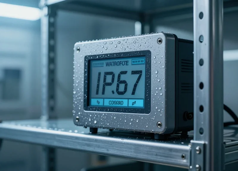
In tobacco packaging environments, the primary threats to RFID reliability are fine organic dust (tobacco fines) and high-frequency mechanical vibration. Ensuring long-term performance requires moving beyond standard hardware to industrial-grade components with at least an IP67 rating, specifically designed to prevent fine particles from infiltrating the reader's internal circuitry. Dust accumulation on antenna surfaces can eventually shift the resonant frequency or cause dielectric loading, which subtly degrades the read range over time if not managed through physical design and scheduled maintenance.
| Environmental Factor | Protection Requirement | Recommended Solution |
|---|---|---|
| Fine Tobacco Dust | IP67 or IP69K Rating | Sealed housings with M12 connectors to prevent particulate ingress. |
| Machine Vibration | 5g to 10g RMS | Use of elastomeric dampeners and Loctite on all mounting hardware. |
| Heat Dissipation | Active/Passive Cooling | Aluminum heat-sync enclosures to prevent thermal throttling in enclosed cabinets. |
| Chemical Cleaning | Corrosion Resistance | 316 Stainless steel brackets to withstand harsh facility wash-down protocols. |
Expert Tip: The 'Electrostatic Dust' Phenomenon. Tobacco dust is highly prone to carrying a static charge during high-speed processing. This charged dust doesn't just sit on the antenna; it creates a 'static blanket' that can cause intermittent electromagnetic interference (EMI) or even trigger false 'tag present' signals in sensitive readers. We recommend using anti-static air knives or localized ionizers near the RFID read point to keep the environment neutralized and the antenna surface clear.
- Vibration Decoupling: Install the RFID reader and antenna on independent struts or use rubber-to-metal bonded isolators to decouple the hardware from the main packaging motor frame.
- Connector Integrity: Standard RJ45 connectors will fail in months due to vibration; always specify M12 X-coded or D-coded connectors for industrial Ethernet and power connections.
- Periodic Calibration: Audit the RSSI (Received Signal Strength Indicator) values monthly. A gradual drop in average RSSI across the same SKU type usually indicates dust buildup on the antenna or a loose mounting bracket.
Can tobacco dust completely block an RFID signal?
No, RFID (UHF) can penetrate organic dust, but extreme accumulation (especially if moist) acts as a dielectric material that detunes the antenna, reducing read accuracy.
How often should I clean the RFID antennas?
In high-speed tobacco lines, a weekly dry-wipe with a microfiber cloth is standard, but air-purged enclosures can extend this to quarterly intervals.
What is the most common point of failure?
Cable fatigue at the connector junction. Ensure all cables have proper strain relief and are rated for high-flex cycles if the reader is mounted on a moving arm.
Validation Protocols: Ensuring 99.9% Read Accuracy
Validation protocols are a systematic series of performance benchmarks designed to ensure that on-metal RFID tags are successfully interrogated at every stage of the tobacco packaging process. To achieve industrial-grade reliability, specifically the 99.9% 'six-sigma' standard, integration must move beyond simple 'it-works' checks into a rigorous framework of static sensitivity analysis, dynamic speed-matching, and electromagnetic interference (EMI) stress testing within the live machinery environment.
- Phase 1: Static Baseline Profiling: Before the line moves, establish the 'Optimal Read Zone' by mapping the RSSI (Received Signal Strength Indicator) of the tag at various orientations within the machine cavity. This identifies the theoretical maximum signal strength before mechanical variables are introduced.
- Phase 2: High-Velocity Dynamic Testing: Run the packaging line at 25%, 50%, and 100% of its rated speed. Because tobacco lines can exceed 500 packs per minute, this phase validates that the 'time-on-target' for the RFID reader is sufficient to complete the full air-protocol handshake.
- Phase 3: Cross-Talk and Collision Audit: Fill the line to maximum density to ensure the reader is only capturing the tag in the 'trigger zone' and not 'ghost-reading' tags from adjacent packages or upstream hoppers.
- Phase 4: Environmental Stress Simulation: Introduce typical industrial stressors, such as high moisture content in the tobacco leaves and the presence of localized metallic dust, to confirm the antenna's tuning remains stable.
| Validation Metric | Target Benchmark | Failure Threshold |
|---|---|---|
| First-Pass Read Rate (FPRR) | 99.95% | < 99.0% |
| Average RSSI Margin | > -50 dBm | < -65 dBm |
| Tag Read Latency | < 15ms | > 35ms |
| False Positive Rate | 0.00% | > 0.01% |
Expert Insight: The 'Dielectric Drift' Factor. Unlike generic dry-goods packaging, tobacco is a hygroscopic organic material. Its moisture content can act as a dielectric load that shifts the resonant frequency of the on-metal tag. Always perform your validation using 'Golden Samples'—finished, tobacco-filled packs—rather than empty boxes. Testing with empty packaging often leads to a false sense of security, as the actual product can detune the antenna by as much as 10-15 MHz once the line is fully operational.
What is the most common cause of missed reads during validation?
In metal-heavy environments, 'Multi-path Fading' is the primary culprit. This occurs when the radio waves reflect off the machine frame and cancel each other out, creating 'null zones' exactly where the package passes.
How many samples are needed for a statistically significant validation?
For a 99.9% accuracy claim, we recommend a minimum of 10,000 consecutive successful reads without a single failure during the Phase 2 dynamic testing.
Should validation be repeated after maintenance?
Yes. Even a 2cm shift in antenna mounting or the replacement of a motor can alter the RF environment. A 'Mini-Validation' (Phase 1 and 2) should be part of the standard post-maintenance SOP.