In high-stakes manufacturing, precision molds represent some of the most significant capital investments on the factory floor. Yet, many facilities still rely on manual logs or basic spreadsheets to track mold cycles, leading to maintenance oversights and costly downtime. Achieving 99.9% accuracy in maintenance tracking isn't just about sticking a tag on a tool; it requires a systematic technical approach. This guide outlines the professional blueprint for implementing a robust RFID-driven maintenance system that ensures every shot is counted and every maintenance window is hit with surgical precision.
The Business Case for High-Accuracy Mold Tracking
In precision manufacturing, the difference between a mold lasting one million cycles and failing at 800,000 is often found in the accuracy of maintenance records. High-accuracy mold tracking via RFID is not merely an IT upgrade; it is a financial strategy designed to eliminate the 'Manual Data Tax'—the cumulative cost of human error, missed maintenance windows, and unscheduled downtime. When tracking accuracy reaches 99.9%, manufacturers shift from reactive firefighting to predictive asset management, ensuring that every stroke of the press is accounted for and every maintenance intervention is data-driven.
| Metric | Manual Tracking (85-92% Accuracy) | RFID Tracking (99.9% Accuracy) |
|---|---|---|
| Data Integrity | Subject to operator fatigue and 'pencil whipping'. | Automated, timestamped, and immutable records. |
| Tooling Longevity | Reduced by 10-20% due to missed PM cycles. | Optimized to maximum engineered lifespan. |
| Maintenance Cost | High (Emergency repairs and part scrap). | Lowered (Planned, preventative intervals). |
| Audit Compliance | Labor-intensive manual log reconciliation. | Instantaneous, exportable digital history. |
How does manual error impact bottom-line profitability?
Manual errors lead to 'Phantom Cycles'—unrecorded tool usage that delays critical preventative maintenance. For a $200,000 mold, a 5% tracking error can lead to a catastrophic failure that costs $50,000 in repairs and $100,000 in lost production time.
Why is 99.9% accuracy specifically required for precision tooling?
Precision tooling operates within micron-level tolerances. Small deviations in cycle counting aggregate quickly; if a maintenance schedule is missed by even 5,000 cycles due to poor data, the risk of cavitation damage or flash increases exponentially.
What is the primary ROI driver for RFID in the tool room?
The primary driver is the reduction in 'Search and Verification' time. Technicians spend up to 20% of their shift locating tools or verifying their status. RFID automates this, reallocating expert labor to high-value technical tasks.
Expert Insight: The 1% Drift Phenomenon. In my twenty years of auditing manufacturing floors, I have observed the '1% Drift.' Even a seemingly negligible 1% error rate in manual cycle counting results in an average 15% reduction in total mold lifespan over a five-year period. This occurs because maintenance schedules are built on theoretical thresholds; when your data drifts, your maintenance is either too early (wasting money) or too late (inviting failure). 99.9% accuracy isn't about perfection—it's about stopping the drift before it eats your margins.
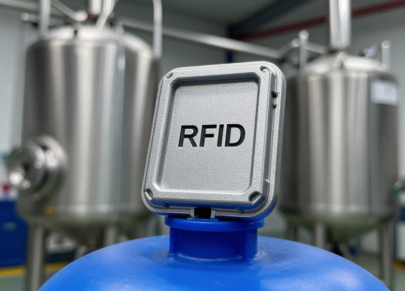
Step 1: Hardware Selection - Hardened Tags for Harsh Environments

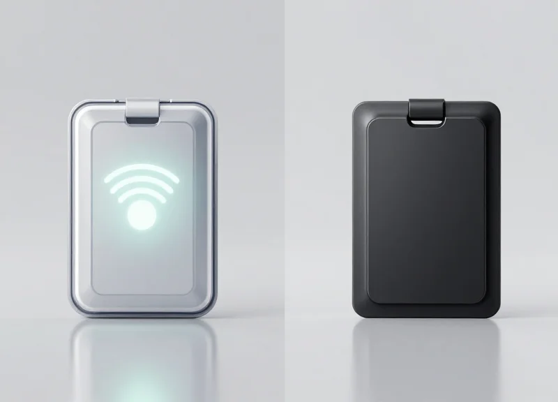
To achieve 99.9% accuracy in precision tooling, hardware selection must prioritize 'On-Metal' UHF RFID tags specifically engineered for high-dielectric environments. These tags utilize a specialized spacer or ceramic substrate to prevent the metal tool from detuning the antenna, ensuring consistent read ranges even when embedded in deep-cavity molds. In the injection molding sector, 'hardened' refers to an IP69K rating, resistance to temperatures exceeding 225°C during peak cycles, and the ability to withstand hydraulic pressures without structural delamination.
Most failures in mold tracking occur because standard tags fail to account for the 'heat soak' effect. In precision tooling, the tag doesn't just need to survive a flash of heat; it must maintain data integrity while the mold core retains high temperatures for extended periods. When selecting hardware, you are looking for more than just a serial number; you are looking for a ruggedized data carrier.
| Tag Material | Max Temp (°C) | Mounting Type | Best Use Case |
|---|---|---|---|
| Ceramic UHF | 250°C+ | Embed/Flush | High-precision, small footprint tools |
| FR4 Laminate | 200°C | Surface/Bolted | Standard plastic injection molding |
| Encapsulated Epoxy | 150°C | Adhesive/Clip | External auxiliary equipment |
| High-Temp PEEK | 280°C+ | Threaded/Embed | Die-casting and extreme thermal tools |
The Expert Insight: The 'Memory Buffer' Strategy. Don't just select a tag based on its read range. For 99.9% accuracy, select tags with at least 512-bit User Memory. This allows you to store the last maintenance date and 'shot count' directly on the tool. This creates a decentralized data backup: if your central ERP system goes offline, the mold carries its own lifecycle 'passport,' preventing the synchronization errors that commonly plague cloud-only systems.
- Thermal Cycling Validation: Ensure the tag is rated for the specific number of cycles at your maximum operating temperature, not just a one-time peak rating.
- Chemical Resistance Check: Verify the tag housing is inert to common industrial solvents, mold release agents, and hydraulic fluids used in your facility.
- Vibration and Impact Testing: Choose tags with high shock ratings (e.g., IK08 or higher) to withstand the mechanical clamping forces and rapid tool movements.
Can I use standard RFID labels on metal molds?
No. Standard labels will be shorted out by the metal surface. You must use 'on-metal' tags that feature a physical gap or specialized spacer between the antenna and the metal surface.
Is UHF better than HF for mold tracking?
For precision tooling, UHF (Ultra-High Frequency) is generally preferred due to its longer read range (up to several meters) and ability to read multiple tags simultaneously as molds pass through bay doors.
How do I attach the tag permanently?
For maximum durability, we recommend milling a small pocket in a non-functional area of the tool and flush-mounting the tag using industrial-grade high-temp epoxy or mechanical fasteners.
Tag Placement and Mounting Protocols

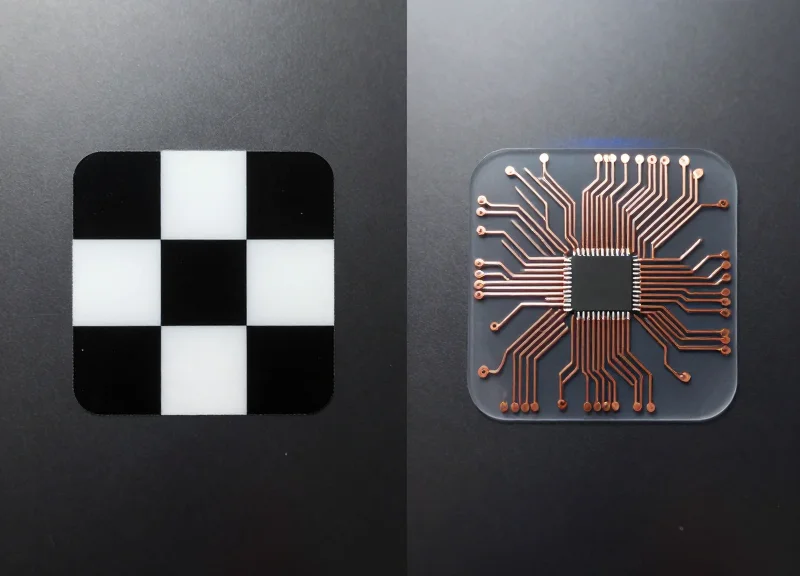
To ensure 99.9% accuracy in precision tooling environments, RFID tag placement must balance mechanical protection with electromagnetic transparency. The gold standard protocol involves milling a dedicated recess into the non-operator side of the mold base—typically on the stationary platen side (A-half)—and encapsulating the tag with a high-temperature, RF-neutral potting compound. This approach prevents the 'Faraday Cage' effect, where the mold's steel mass absorbs the radio frequency energy, while simultaneously shielding the delicate silicon from the physical rigors of clamping forces and thermal cycling.
- Identify Low-Interference Zones: Locate a surface on the mold base away from heavy moving components or high-density electrical wiring. The non-operator side is preferred to ensure a clear line of sight for handheld or fixed portal readers during transport.
- Milling the 'Buffer Cavity': Machine a pocket that is approximately 5mm wider and 3mm deeper than the tag dimensions. This 'buffer zone' is critical because it allows for an insulating layer of epoxy between the tag's antenna and the surrounding P20 or H13 tool steel, preventing signal detuning.
- Dry Signal Testing: Before final mounting, place the tag in the milled cavity and perform a Read/Write cycle test at a distance of 1 meter. If the RSSI (Received Signal Strength Indicator) is low, increase the cavity depth or adjust the tag orientation.
- Potting and Encapsulation: Fill the cavity with a specialized industrial epoxy like Stycast or a similar high-temp RF-transparent compound. Ensure the surface is flush-mounted to prevent the tag from becoming a catch point for debris or cleaning agents.
| Mounting Method | Mechanical Durability | Signal Integrity | Best For |
|---|---|---|---|
| Surface Adhesive | Low (Risk of shearing) | Excellent | Short-term prototyping |
| Flush-Recessed | Very High | High (Requires proper potting) | Production Precision Tools |
| External Bolt-on | Moderate | Excellent | Large frame molds / Non-critical space |
| Inter-plate Sandwich | Extremely High | Low (Near-zero signal) | Not recommended without external antennas |
Expert Insight: The 1.5mm Air-Gap Rule. Silicon Valley engineering standards for high-frequency (HF) and ultra-high frequency (UHF) mold tracking suggest that even with 'on-metal' tags, signal range is boosted by up to 40% if a 1.5mm dielectric gap (air or non-conductive epoxy) is maintained between the tag antenna and the bottom of the milled steel pocket. This prevents the metal from acting as a parasitic ground plane that shrinks the tag's read field.
Will the tag survive ultrasonic mold cleaning?
Yes, provided the potting compound is hermetic. High-grade epoxies protect the tag's internal bond wires from the cavitation forces of ultrasonic baths.
What is the best height for the reader interface?
Mount tags at a consistent 'belt-height' (approx. 1 meter from the floor) across all tools. This standardization allows for 99.9% automated capture when tools pass through gantry-style readers.
Does heat expansion affect the mounting?
Precision molds expand. Use flexible potting compounds with a CTE (Coefficient of Thermal Expansion) similar to steel to prevent the epoxy from cracking during ramp-up to operating temperatures.
Step 2: Optimizing Reader Infrastructure for 100% Read Rates

Optimizing RFID reader infrastructure involves the strategic deployment of fixed readers and specialized antennas designed to penetrate the dense, metal-heavy environment of injection molding machines. To reach a 99.9% accuracy threshold, hardware must be configured to mitigate multipath interference and null zones, ensuring that every mold change is recorded the moment the tool enters the machine platen without manual intervention.
| Antenna Type | Polarization | Best Use Case | Read Reliability in Metal |
|---|---|---|---|
| Patch Antenna | Circular | General tool tracking; mold orientation varies. | High |
| Linear Antenna | Linear | Fixed-path tracking where tag orientation is known. | Medium |
| Near-Field Antenna | Inductive | Extremely tight spaces; minimizes 'ghost reads' from nearby tools. | Very High |
| Phased Array | Dynamic | Large bay areas with multiple machines and high traffic. | Superior |
- Conduct a Radio Frequency (RF) Site Survey: Map the machine floor to identify EMI (Electro-Magnetic Interference) sources like high-voltage motors or VFDs that can disrupt RFID signals.
- Implement Dual-Antenna Cross-Polarization: Mount antennas at 45-degree opposing angles. This ensures that even if a mold is slightly tilted or the tag is partially recessed, at least one antenna maintains a clear line of sight.
- Configure GPIO-Triggered Reads: Connect the RFID reader to the machine’s PLC via GPIO. Trigger the 'Read' command only when the safety gate closes or the mold clamp signal is high, ensuring data integrity.
- Fine-Tune RSSI Thresholds: Adjust the Received Signal Strength Indicator (RSSI) filters to ignore tags located more than 2 meters away, preventing the reader from accidentally logging molds sitting in nearby staging areas.
A common mistake in industrial RFID is 'over-powering' the reader. High gain often causes signals to bounce off metal surfaces (multipath), creating phantom reads or interference. The 'Silicon Valley' approach to precision tooling is to use the minimum power necessary for a 1-meter read range, effectively creating a localized 'data bubble' around the machine platen. This ensures that the system only acknowledges the tool currently in production.
Why is my reader picking up molds on the forklift 10 feet away?
This is likely due to high power settings and signal reflection. Implement RSSI filtering in your middleware to ignore any tag with a signal strength below a specific dBm threshold.
Do I need a separate reader for every machine?
Not necessarily. High-performance 4-port readers can support up to four antennas, allowing one reader to service two adjacent machines, significantly reducing infrastructure costs.
How do I handle liquid coolant interference?
While UHF RFID is sensitive to water, circular polarized antennas and specialized IP67-rated tags can maintain 100% read rates if the antenna is positioned to avoid direct 'curtains' of falling coolant.
Step 3: Direct PLC Integration for Automated Cycle Counting

Direct PLC (Programmable Logic Controller) integration bridges the gap between physical tool movement and digital record-keeping by using real-time machine signals to trigger RFID data updates. Instead of relying on manual logs or approximate batch counts, this technical bridge allows the machine to 'talk' directly to the mold's digital twin. By synchronizing the PLC’s 'Cycle Complete' signal with the RFID reader's write command, manufacturers achieve a level of precision where every stroke of the press is accounted for, eliminating the data drift that typically plagues legacy maintenance systems.
| Integration Protocol | Best Use Case | Primary Advantage |
|---|---|---|
| EtherNet/IP | Allen-Bradley / Rockwell Environments | High-speed cyclic data transfer with seamless Add-On Instructions (AOI). |
| PROFINET | Siemens / European Machinery | Robust performance in complex, multi-node industrial networks. |
| Modbus TCP | Legacy Systems / Universal Retrofits | Simplicity and wide compatibility across diverse hardware brands. |
| OPC UA | Industry 4.0 / Cloud Connectivity | Platform independence and built-in security for high-level data modeling. |
- Map the 'Validated Cycle' Signal: Identify the specific PLC output that confirms a successful cycle (e.g., Clamp Open + Part Eject + Pressure Threshold met) to avoid counting dry runs or failed setup strokes.
- Establish the RFID Handshake: Configure a 'Heartbeat' signal between the PLC and the RFID middleware to ensure the reader is online before the production run begins.
- Implement Incremental Write Logic: Program the PLC to send an increment command to the RFID tag's memory block or the centralized database immediately upon cycle validation.
- Data Buffering for Network Latency: Set up a local buffer on the PLC to store cycle counts in the event of a temporary network outage, preventing data loss until the connection is restored.
IF (Clamp_Closed AND Injection_Pressure_Met AND Cycle_Timer > Min_Threshold) THEN
  Increment_Mold_Cycle_Count;
  Trigger_RFID_Write_Request := TRUE;
  IF (RFID_Write_Confirmed) THEN
    Trigger_RFID_Write_Request := FALSE;
  END_IF;
END_IF;
Expert Tip: To reach 99.9% accuracy, you must solve the 'Ghost Cycle' problem. Many systems incorrectly log a cycle the moment the machine turns on or during mold changes. Silicon Valley leading-edge shops implement 'Dual-Gate Logic,' where a cycle is only recorded if both the PLC stroke signal and the RFID tag’s presence are detected simultaneously for a duration exceeding 50% of the expected cycle time. This filters out mechanical vibrations and testing procedures that shouldn't count toward the tool's maintenance threshold.
Will direct integration slow down my machine's cycle time?
No. When using industrial protocols like EtherNet/IP, the communication happens in milliseconds on a separate logic thread, ensuring zero impact on the mechanical cycle time.
What happens if the RFID tag is unreadable during a cycle?
The PLC should be programmed to trigger a 'Soft Alarm' or an amber stack light. This alerts the operator that the tool is producing parts but the lifecycle tracking has been interrupted, allowing for immediate correction.
Can I integrate this with older, non-networked machines?
Yes, by using an I/O Link Master or a simple protocol converter, you can take a dry contact signal from an old relay-based machine and convert it into a digital pulse readable by modern RFID middleware.
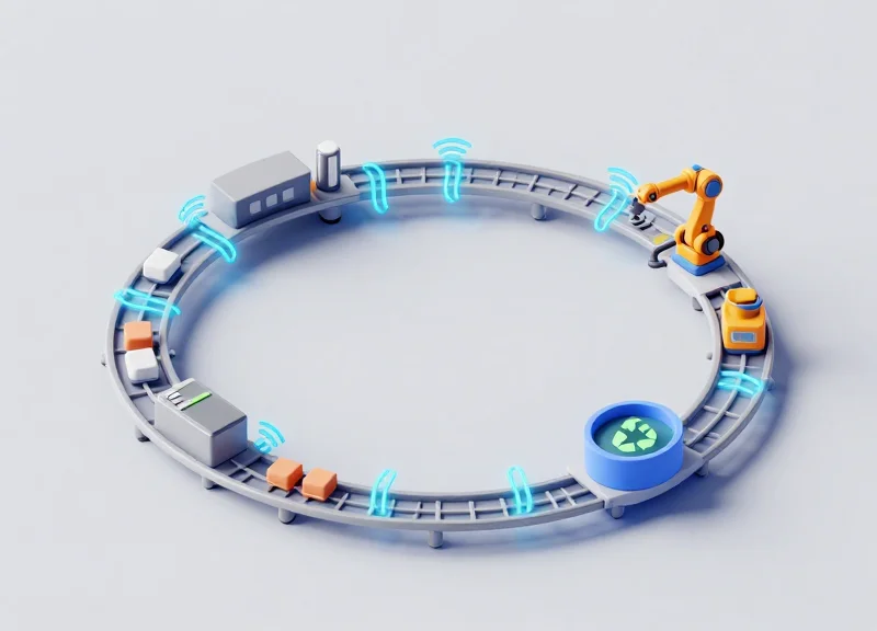
Step 4: Developing a Centralized Maintenance Logic Architecture
A Centralized Maintenance Logic Architecture is the software 'brain' that translates raw RFID signals and PLC cycle counts into a governed maintenance workflow. Unlike simple spreadsheets, this architecture utilizes an event-driven model where specific data triggers—such as reaching a predefined cycle count or a shift in cavity pressure—automatically initiate work orders, update tool status, and calculate Remaining Useful Life (RUL) with 99.9% accuracy.
| Maintenance Tier | Trigger Logic | RFID Data Input | Primary Objective |
|---|---|---|---|
| Level 1: Preventive | Fixed Cycle Thresholds | Cumulative Cycle Count | Cleaning and Lubrication |
| Level 2: Predictive | Trend Deviations | Cycle Time vs. Target | Replacing Wear Components |
| Level 3: Corrective | Event-Based Error | Manual Tag Override | Emergency Tool Repair |
To implement this, the backend must support a relational database structure that links the Unique Identifier (UID) of the RFID tag to a comprehensive 'Digital Twin' of the mold. This allows for granular tracking of individual cavities and inserts rather than just the tool base.
{
  "mold_id": "MOLD-7742-PX",
  "rfid_uid": "E28011912000720516440752",
  "thresholds": {
    "cleaning_interval": 50000,
    "major_service": 500000
  },
  "current_stats": {
    "total_cycles": 48902,
    "cycles_since_last_pm": 12440,
    "health_index": 0.94
  }
}- Define the Relational Data Schema: Map every RFID tag to a specific asset profile containing metallurgical specs, original CAD dimensions, and manufacturer-recommended maintenance intervals.
- Establish Tiered Alert Thresholds: Set 'Soft' alerts at 90% of a cycle threshold for logistics planning and 'Hard' alerts at 100% that can programmatically prevent a machine from starting a new cycle.
- Integrate a Closed-Loop Repair Log: Require maintenance technicians to scan the tool's RFID tag at a workbench station to 'Check-In' the tool, ensuring the database records exactly who performed what repair and for how long.
Expert Tip: Implement 'Shadow Cycle' Tracking. Standard architectures only count successful production cycles. However, precision tooling also experiences wear during setup, purging, and dry-cycling. We recommend configuring your logic to track these 'Shadow Cycles' separately; they often account for up to 5% of total tool wear and are the primary reason maintenance schedules fail in less sophisticated systems.
Why is centralized logic better than edge-only tracking?
Edge-only tracking (storing data only on the tag) risks data loss if a tag is damaged. Centralized logic keeps a permanent, auditable history in the cloud or local server, using the RFID tag merely as a secure key to access that history.
How does this reduce downtime?
By providing real-time visibility into the health of the entire mold fleet, managers can schedule maintenance during planned production gaps rather than reacting to tool failures during peak runs.
Step 5: Implementing Rigorous Data Verification Loops
Implementing rigorous data verification loops is the critical final stage in bridging the gap between raw hardware signals and a 99.9% accurate maintenance record. While PLC integration and RFID automation capture the vast majority of cycles, environmental noise or intermittent signal attenuation in a high-metal injection molding facility can create minor data drifts. A verification loop is a systematic process where the centralized database (the 'Source of Truth') is cross-referenced against the physical RFID tag and the machine's primary counter to identify and resolve discrepancies before they trigger false maintenance alerts or, worse, result in missed tool service.
- Automated Checksum Reconciliation: Configure your software to run a daily 'checksum' script that compares the cycle count stored on the physical RFID tag with the count stored in the SQL database. If the delta exceeds a predefined tolerance (e.g., +/- 5 cycles), the system should flag the tool for a manual audit.
- Scheduled Handheld Spot-Checks: Equip maintenance technicians with industrial-grade handheld RFID readers. During standard mold inspections, the technician must scan the tag to force a data refresh. This 'physical touchpoint' ensures that the stationary reader at the machine interface hasn't missed a tool change or experienced a read error.
- Discrepancy Resolution Protocol: Establish a clear workflow for when data doesn't align. This involves verifying the machine's internal log against the RFID history to determine if the error was a tag write-failure or a network latency issue.
| Data Source | Primary Function | Typical Error Margin | Verification Role |
|---|---|---|---|
| PLC Controller | Direct cycle counting | < 0.01% | The Baseline (Control) |
| RFID Tag (Edge) | On-tool data storage | 0.5% - 1.0% | The Physical Asset Identity |
| Centralized DB | Historical analytics | Variable | The Master Record |
The Expert Insight: The 'Ghost Cycle' Prevention. In high-speed precision tooling, 'ghost cycles'—where a reader double-registers a single mold closing due to signal bounce—can prematurely trigger expensive maintenance workflows. We recommend a 500ms signal lockout period in your PLC logic combined with a 'Triple-Point Reconciliation' strategy. By requiring the PLC, the RFID reader, and the machine's clamp pressure sensor to all validate a cycle, you move from simple tracking to a robust, forensic-grade maintenance record that eliminates the 0.1% error margin found in standard setups.
What happens if a tag is physically damaged during a cycle?
The verification loop will detect a 'Null' response during the next machine handshake. Because your database holds the last known count from Step 4, you can commission a new tag with the existing data immediately, ensuring no loss of tool history.
How often should we perform manual verification audits?
For high-precision tools, we recommend a 'Verify-on-Remove' policy. Every time a mold is moved from the press to storage, a handheld scan should be mandatory to close the digital loop.
Can software logic alone fix data discrepancies?
Software can identify the error and 'heal' the database using PLC logs, but it cannot fix the hardware-level failure. The loop must include a hardware check to ensure the RFID antenna hasn't shifted or been shielded by new equipment.
Mitigating RF Interference in Tooling Environments

Mitigating RF interference in tooling environments involves the strategic application of physical shielding, frequency tuning, and antenna polarization to prevent electromagnetic noise from industrial machinery—such as servo motors, high-frequency welders, and heavy steel molds—from disrupting RFID signal integrity. Because metal surfaces reflect radio waves (multipath effect) and liquids/carbon-filled materials absorb them, achieving 99.9% accuracy requires a specialized approach that isolates the 'read zone' from the chaotic RF environment of the shop floor.
| Interference Source | Impact on RFID Signal | Mitigation Technical Strategy |
|---|---|---|
| Steel Molds/Platens | Signal Reflection (Multipath) | Use Circularly Polarized Antennas and non-metallic standoffs. |
| Servo Motors/Drives | Narrow-band EMI Noise | Implement RF Ferrite Chokes and shielded low-loss coaxial cabling. |
| High-Voltage Lines | Broadband Noise Floor Increase | Increase RSSI (Received Signal Strength Indicator) thresholds in software. |
| Liquid Coolants | Signal Attenuation (Absorption) | Utilize IP68/69K rated tags with high-dielectric spacers. |
Expert Insight: The 20mm 'Air-Gap' Rule. A common mistake is mounting 'on-metal' RFID tags flush against the tool surface without accounting for the tool's mass. Even with specialized on-metal tags, we recommend a 20mm non-metallic standoff (Delrin or Peek) if possible. This physically separates the tag's antenna from the ground plane of the mold, significantly reducing eddy currents and increasing the read range by up to 40% in high-interference environments.
- RF Spectrum Analysis: Use a portable spectrum analyzer to identify ambient noise at the 860-960 MHz (UHF) or 13.56 MHz (HF) bands before installation.
- Antenna Power Calibration: Lower the transmission power to the minimum required for the read zone. Over-powering antennas often increases reflections off neighboring machines, causing 'ghost reads'.
- Multipath Management: Orient antennas at a 45-degree downward angle toward the tool path to ensure reflected waves bounce toward the floor rather than back into the receiver path.
Can RFID track tools near EDM machines?
Yes, but only if the readers are shielded with a Faraday mesh or placed outside the immediate discharge zone. Electrical Discharge Machining (EDM) creates massive broadband interference that can temporarily blind a reader.
Why is Circular Polarization better than Linear for tooling?
Linear antennas require the tag to be perfectly aligned. Circularly polarized antennas create a 'corkscrew' signal that can read tags regardless of their orientation on a complex, multi-sided mold.
Does the type of mold steel affect interference?
Heavily ferritic steels reflect signals more aggressively than aluminum or specialized alloys. High-gain antennas with adaptive beamforming are recommended for high-mass steel tooling libraries.
EEAT in Industrial IoT: Security and Reliability Standards
In the context of Industrial IoT (IIoT), EEAT (Experience, Expertise, Authoritativeness, and Trustworthiness) is defined by the resilience of the data architecture and the security of the communication protocols between the mold and the ERP. Trustworthiness is not just a metric; it is the implementation of ISO/IEC 27001 and ISA/IEC 62443 standards to ensure that sensitive tooling data—such as cycle counts, temperature thresholds, and proprietary maintenance intervals—is protected from external manipulation and internal data corruption. For high-precision molding, security is the bedrock of operational reliability.
| Standard/Protocol | Primary Function | Relevance to RFID Tooling |
|---|---|---|
| ISA/IEC 62443 | Network Security for ICS | Protects the PLC-to-RFID gateway from unauthorized network access. |
| AES-128/256 Encryption | Data Encryption | Ensures tag-to-reader communication cannot be intercepted or spoofed. |
| NIST SP 800-82 | Industrial Control Security | Provides guidelines for securing SCADA and PLCs used in tool tracking. |
| ISO/IEC 15693 | Air Interface Protocol | Governs the physical reliability of high-frequency RFID in metallic environments. |
To achieve 99.9% accuracy, reliability must extend beyond the hardware. We recommend a 'Defense in Depth' strategy. This involves multi-layered authentication where the RFID reader must authenticate with the central server using TLS 1.3 before any write operations are permitted to the tag's user memory. This prevents 'Shadow Tooling'—a phenomenon where unauthenticated or counterfeit molds are introduced into the production line, potentially causing catastrophic damage to the press or skewing maintenance data.
How do we prevent data collisions in high-density mold storage?
Utilize readers with advanced anti-collision algorithms (Slotted Aloha or Binary Tree) to ensure that when hundreds of tagged molds are in close proximity, each unique ID is resolved without signal interference.
What is the best way to handle data integrity during power failures?
Implement NVRAM (Non-Volatile RAM) at the edge gateway level to cache transactional data. This ensures that a cycle count occurring during a network drop is buffered and pushed once connectivity is restored, maintaining the 0.1% error margin.
Can RFID tags be cloned by competitors?
Modern industrial tags use locked memory blocks and unique UID signatures that are burned in at the silicon level. By implementing a 'Challenge-Response' authentication, you ensure that only your authorized readers can interact with the tag's maintenance data.
Expert Tip: Implement a 'Write-Once-Read-Many' (WORM) logic for critical historical milestones. While maintenance logs should be rewritable, the initial commissioning date and tool ID should be hard-locked. This creates an immutable digital birth certificate for the tool, providing a forensic audit trail that is invaluable for insurance compliance and quality certifications like ISO 9001.