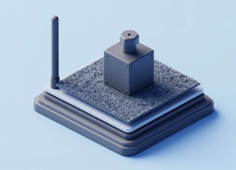
In modern retail, exhibition, and industrial environments, the demand for invisible asset tracking often conflicts with the harsh realities of physical traffic. Standard RFID antennas are frequently crushed or damaged when placed under flooring subjected to heavy foot traffic or equipment. Engineered to withstand 500kg loads, ruggedized under-carpet RFID antennas offer a discrete solution without compromising on structural integrity. This guide provides a comprehensive technical walkthrough for installing these high-capacity systems, ensuring your infrastructure remains both invisible and indestructible.
The Engineering Behind 500kg Load Ratings

A 500kg load rating signifies that an under-carpet RFID antenna can withstand half a metric ton of static pressure without compromising the internal PCB or signal integrity. This durability is achieved through a combination of high-impact engineering plastics, internal structural ribbing, and precision-poured potting compounds that redistribute 'point-load' energy—such as that from a heavy equipment wheel or a high-heel shoe—across the entire surface area of the device to prevent internal component crushing.
To achieve this level of resilience, engineers move beyond standard ABS enclosures. Ruggedized antennas typically utilize fiber-reinforced polycarbonates or specialized thermoplastic elastomers (TPE). These materials are selected based on their Young's Modulus, a measure of stiffness, ensuring that the enclosure undergoes minimal deflection when compressed. Excessive deflection is the primary cause of solder joint failure in RFID systems, as it creates mechanical stress hotspots on the antenna's circuit board.
| Load Class | Weight Threshold | Typical Use Case | Structural Requirement |
|---|---|---|---|
| Standard | 50kg | Residential Foot Traffic | Thin ABS Enclosure |
| Heavy Duty | 200kg | Retail / Airport Concourses | Reinforced Polycarbonate |
| Ruggedized | 500kg+ | Industrial / Trade Shows | High-Density Composite + Potting |
One often overlooked aspect of 500kg engineering is 'Void-Fill' technology. Even the strongest shell will fail if there is air inside the unit. High-end ruggedized antennas use vacuum-poured epoxy or silicone potting materials. This creates a solid, monolithic block where the internal components are suspended in a medium with similar density to the shell, ensuring that pressure is transferred through the potting rather than being absorbed by the sensitive ceramic antenna patches.
How does 500kg load capacity affect RF performance?
High-density materials can shift the antenna's center frequency (detuning). Engineering teams must pre-calculate this dielectric constant shift to ensure the antenna remains tuned to 865-928 MHz even under maximum compression.
What is the difference between static and dynamic load ratings?
Static load is a stationary weight, while dynamic load involves movement. A 500kg rated antenna is tested for 'Rolling Loads' to simulate equipment moving across the surface without shearing the internals.
Expert Insight: When reviewing technical specifications, look for the 'Shore Hardness' of the outer casing. A Shore D rating of 80 or higher is typically required for 500kg loads. This hardness ensures that point-load energy is dissipated horizontally through the surface rather than penetrating vertically into the delicate internal RF traces. Additionally, check for a Coefficient of Thermal Expansion (CTE) match between the casing and the PCB to prevent stress fractures during temperature swings.
Pre-Installation Site Assessment
A successful deployment of ruggedized under-carpet RFID antennas begins with a comprehensive pre-installation site assessment, which involves analyzing subfloor structural integrity, measuring moisture levels to prevent RF attenuation, and mapping electromagnetic interference (EMI) that could disrupt 500kg-load-rated hardware. This critical phase ensures that both the mechanical housing and the internal RF components operate within their design specifications, preventing premature failures caused by point-load stress or signal detuning.
| Subfloor Material | RF Impact | Structural Support (500kg) | Mitigation Strategy |
|---|---|---|---|
| Cured Concrete | Low Reflection | Excellent | Level surface grinding |
| Rebar-Reinforced Slab | High Interference | Superior | Use shielding gaskets |
| Wood/Plywood | Moderate Absorption | Variable | Cross-beam reinforcement |
| Raised Access Floor | Signal Multi-path | Moderate | Verify pedestal load limits |
The most overlooked variable in under-carpet installations is the 'Dielectric Loading' effect caused by floor moisture. Even if a floor appears dry, concrete pores can hold significant water vapor. This moisture acts as a parasitic load, shifting the antenna's resonant frequency and reducing read range by as much as 40%. Expert Tip: Always use a non-destructive moisture meter to ensure the relative humidity (RH) of the slab is below 3%. If higher, a moisture-blocking vapor barrier is mandatory, provided it is non-metallic to avoid blocking the RF signal.
- Planar Leveling Check: Use a 3-meter straightedge to identify high spots or depressions. For 500kg load ratings, the floor must be flat within 3mm over a 3-meter span to prevent 'bridging,' where the antenna housing takes the full force of a load without subfloor support.
- Baseline RF Noise Mapping: Utilize a spectrum analyzer to identify ambient noise in the 860-960 MHz range. Common culprits include nearby conveyor motors or poorly shielded industrial lighting.
- Traffic Pattern Analysis: Identify the 'Primary Load Path.' Antennas should be placed where wheels or pallet jacks are most likely to pass over them squarely, rather than at sharp angles which increase lateral shear stress.
Can I install these antennas over metal floor plates?
No, direct installation on metal causes signal reflection and detuning. You must use a high-density polyethylene (HDPE) spacer of at least 10mm to provide an RF buffer.
How does carpet thickness affect the 500kg load rating?
While the carpet doesn't change the antenna's rating, high-pile carpets can create a 'sinking' effect that puts uneven pressure on the housing edges. Low-profile commercial-grade tiles are recommended.
What is the 'Point Load' risk for RFID antennas?
A 500kg load on a pallet jack wheel (small surface area) creates much higher pressure than a 500kg flat crate. Assessment must prioritize the highest potential point load expected in the facility.
Selecting the Correct Under-Carpet Ruggedized Antenna

To select the correct under-carpet ruggedized antenna, you must prioritize a 'three-pillar' evaluation: mechanical height (typically <12mm), load-bearing certification (minimum 500kg point load), and RF transparency through floor materials. The ideal antenna is not just 'thin,' but engineered with a high-impact polymer housing that prevents the internal radiating elements from deforming under foot traffic or heavy machinery, as even a 1mm shift in element spacing can detune the antenna and plummet read rates.
| Specification | Recommended Value | Impact on Performance |
|---|---|---|
| Polarization | Circular (RHCP/LHCP) | Ensures tag readability regardless of orientation on the floor. |
| Antenna Gain | 5.5 dBi to 9.0 dBi | Higher gain overcomes signal attenuation from dense carpet fibers. |
| Profile Height | 8mm - 12mm | Prevents tripping hazards and ensures a 'seamless' floor aesthetic. |
| Frequency Range | Global (860-960 MHz) | Allows for international deployment without hardware changes. |
While gain and height are standard metrics, the Dielectric Shifting Factor is a critical, often overlooked technical detail. When an antenna is placed under a carpet and secured with adhesive, the surrounding material acts as a dielectric. This can shift the antenna's center frequency away from its tuned resonance. Always select an antenna designed with a 'ground-plane insensitive' architecture, which maintains frequency stability even when placed directly on concrete or under moisture-retentive recycled-fiber carpets.
Why is Circular Polarization mandatory for under-carpet use?
Tags on the floor (on shoes or assets) rarely maintain a consistent orientation. Circular polarization allows the antenna to capture the backscatter signal regardless of whether the tag is vertical, horizontal, or skewed, which is impossible with linear antennas.
Does a higher dBi gain always mean better performance?
Not necessarily. While higher gain increases read distance, it also narrows the beamwidth. For under-carpet use, a mid-range gain (approx. 6 dBi) is often preferred to provide a wider 'read zone' for foot traffic.
Can I use a standard thin antenna if the load is under 100kg?
No. Standard antennas are not rated for 'point loads.' A person walking in high heels can exert pressure exceeding 200kg per square inch, which will crack standard housings and destroy the internal antenna patch.
Veteran Insider Tip: When comparing spec sheets, look for the 'Axial Ratio' at the boresight. A low axial ratio (under 3dB) indicates high-quality circular polarization. In under-carpet environments where reflections are high, a low axial ratio significantly reduces the 'dead zones' where tags typically fail to read.
Subfloor Preparation and Trenching Techniques

To maintain a seamless floor surface capable of supporting 500kg loads, subfloor preparation must focus on creating a recessed 'pocket' or trench that matches the antenna's specific dimensions. This ensures that the ruggedized antenna sits flush with the subfloor, allowing the carpet or tiles to lay flat without visible crowning. Failure to properly trench the subfloor leads to concentrated pressure points, which can cause carpet delamination or premature antenna failure despite the ruggedized housing.
| Subfloor Type | Preparation Method | Recommended Depth | Load-Bearing Considerations |
|---|---|---|---|
| Concrete / Screed | Diamond Blade Saw-Cut & Chipping | 10mm - 15mm | Self-leveling epoxy pour to stabilize base. |
| Plywood / Timber | Plunge Router with Guide Rail | Matched to Antenna Thickness | Reinforcement of joists if depth exceeds 30% of thickness. |
| Raised Access Floors | Panel Replacement or Custom Cutting | Flush Mount Bracket | Verify panel load rating (e.g., CISCA standards). |
- Precise Layout Mapping: Mark the antenna footprint and cable pathways using a chalk line. Add a 5mm tolerance on all sides to allow for thermal expansion and cabling connectors.
- Controlled Depth Trenching: Use a plunge router for wood or a wet-shroud concrete saw for masonry. Maintain a consistent depth to prevent the antenna from 'rocking' under 500kg rolling loads.
- Channeling for Coaxial Cables: Route cables in 10mm wide channels. Ensure all turns have a minimum 50mm radius to prevent signal attenuation and physical stress on the LMR-195 or LMR-240 cables.
- Surface De-burring and Cleaning: Remove all debris and sharp protrusions. Even a 2mm pebble can create a high-pressure point that damages the antenna's radome over time.
Expert Insight: The 'Compression Shimming' Technique. In high-traffic environments, even slight variances in trench depth can cause the antenna to shift. We recommend using 0.5mm stainless steel shims or high-density HDPE spacers to 'true' the antenna's base. This ensures 100% surface contact between the antenna and the subfloor, which is critical for distributing 500kg point loads across the entire structural chassis of the device, rather than just the corners.
How do I handle moisture in concrete trenches?
Always apply a vapor barrier coating or a rapid-dry waterproofing membrane to the interior of the trench before installing the antenna to prevent RF interference from moisture accumulation.
Can I install antennas without trenching?
Only if using a ramped transition strip; however, for 500kg loads, trenching is mandatory to ensure the antenna is not an obstacle for heavy machinery or industrial carts.
What is the best way to secure the antenna in the trench?
Use a non-permanent, high-shear-strength adhesive or mechanical countersunk fasteners. Avoid expanding foam, as it can lift the antenna out of alignment during the curing process.
Cable Management in High-Traffic Zones

Cable management in high-traffic zones involves protecting sensitive RF coaxial lines from the destructive forces of vertical compression and lateral shear. In environments where 500kg rolling loads (such as heavy forklifts or medical imaging equipment) are present, cables must be housed within recessed, rigid-walled conduits or specialized ultra-low-profile floor channels. This ensures that the physical weight is borne by the subfloor and conduit structure rather than the cable’s dielectric and shielding, which would otherwise suffer from 'crush-induced' signal attenuation or total failure.
| Conduit Material | Load Resistance | RF Interference Level | Best Use Case |
|---|---|---|---|
| Reinforced PVC | High (up to 300kg) | Zero (Non-conductive) | Standard warehouse aisles |
| Extruded Aluminum | Ultra-High (500kg+) | Low (Requires grounding) | Heavy industrial/Manufacturing |
| Braided Steel Sleeve | Moderate | Variable | Flexible routing around corners |
- Determine the 'Shear-Free' Route: Map out cable paths that avoid direct intersections with primary wheel paths. If crossing is necessary, use a perpendicular 'T-bone' approach to minimize the duration of pressure.
- Execute Deep-Trench Recessing: Utilize a concrete saw to create a 15mm deep trench. This allows the conduit to sit flush or slightly below the subfloor surface, preventing any 'speed bump' effect that increases impact force.
- Implement Sweeping Radius Turns: Never use 90-degree elbows. High-traffic vibration can cause the cable to rub against sharp internal corners. Use a minimum 10x cable diameter bend radius for all turns.
- Void Sealing and Stabilization: Fill the gaps around the conduit with a non-shrinking epoxy resin. This prevents the conduit from shifting or 'chattering' when heavy loads pass over it, which is a common cause of cable fatigue.
The Expert Tip: The 'Sacrificial Shield' Strategy. In 20 years of Silicon Valley deployments, we’ve found that even the best conduits can eventually fail under repetitive 500kg stress. Always pull a 'sacrificial' nylon pull-string alongside your coax. If a cable ever needs replacing due to extreme environment degradation, you can swap it in minutes without ripping up the carpet or re-trenching the concrete. Furthermore, consider LMR-240-Ultraflex cables for these zones; their stranded center conductors handle the micro-vibrations of heavy traffic significantly better than solid-core alternatives.
Can I run power cables in the same conduit as RFID coax?
No. To avoid Electromagnetic Interference (EMI) and maintain data integrity, RFID coaxial cables should maintain at least 10cm of separation from high-voltage power lines.
What happens if the cable is slightly crushed?
Even a minor deformation changes the characteristic impedance (usually 50 ohms). This causes 'Standing Wave Ratio' (SWR) spikes, which reflect power back into the reader and reduce read range significantly.
Is rigid metal conduit (RMC) recommended?
While RMC offers the best protection, it can act as an antenna and cause unwanted RF reflections. Aluminum or high-density plastic is generally preferred for RFID deployments.
RF Calibration and Signal Optimization

RF calibration for under-carpet antennas is the process of adjusting RFID reader power, sensitivity, and frequency parameters to compensate for the Signal-to-Noise Ratio (SNR) degradation caused by floor coverings and subfloor reflections. Because ruggedized antennas must transmit through dense carpet fibers and often sit atop conductive concrete or metal decking, signal optimization ensures consistent tag detection without 'ghost reads' or dead zones. Successful calibration involves balancing the link budget to account for the specific dielectric constant of the carpet material and the RF absorption rates of the surrounding environment.
| Carpet Material | Dielectric Constant (εr) | Signal Attenuation (dB/cm) | Calibration Adjustment |
|---|---|---|---|
| Low-Pile Nylon | 1.7 - 2.0 | 0.5 - 1.2 | Increase Power +1dBm |
| Heavy Wool/Plush | 2.5 - 3.1 | 2.0 - 3.5 | Increase Power +3dBm; Lower RSSI |
| Rubber-Backed Tiles | 3.5 - 5.0 | 4.0 - 6.0 | High Power; Wide Beam Tuning |
| Conductive/Anti-Static | Variable | Extreme | Shielded Cables; Frequency Hopping |
Expert Insight: The 'Dynamic Dielectric Shift' Under Load. A factor often overlooked in laboratory settings is how 500kg loads physically compress the carpet fibers. Under high pressure, the air gaps between fibers (with a dielectric constant of ~1.0) are eliminated, effectively increasing the carpet's density and its dielectric constant. This causes a momentary shift in the antenna's resonance. To mitigate this, calibrate your system using a 'peak-load' baseline—test the signal while a heavy trolley or weighted cart is positioned directly over the antenna to ensure the read zone remains stable during actual use.
- Baseline Noise Floor Mapping: Run a site survey with the reader in 'Listen Mode' to identify ambient EMI from nearby machinery or electrical conduits. Set your noise floor threshold at least 15dBm below your target tag RSSI.
- Incremental Power Ramp-Up: Start at 20dBm and increase in 1dBm increments until 100% read rate is achieved on a floor-level tag. Avoid jumping straight to maximum power (30dBm+), as this creates multipath interference against concrete subfloors.
- RSSI Threshold Filtering: Configure Received Signal Strength Indicator (RSSI) filters to ignore weak signals. This ensures that tags carried by pedestrians nearby aren't erroneously logged as 'on-floor' transitions.
- Polarization Alignment: If using circular polarized antennas, verify that the 'sense' (LHCP/RHCP) is optimized for the tag orientation, especially if the 500kg load includes metallic objects that might cause phase reversal.
How does moisture in the carpet affect calibration?
Moisture significantly increases the dielectric constant and signal absorption. If the carpet is damp from cleaning or humidity, you may need to increase the reader's sensitivity or wait for the material to dry for accurate calibration.
Can I use the same settings for all antennas in a bay?
Rarely. Due to varying subfloor compositions (e.g., rebar proximity), each antenna should be calibrated individually to ensure uniform zone coverage.
What is the ideal RSSI for under-carpet tags?
Ideally, you want a stable RSSI between -50dBm and -65dBm for tags directly on the antenna surface for high-reliability industrial applications.
Load Testing and Performance Validation

Load testing for under-carpet RFID antennas is the process of verifying that the hardware can withstand heavy mechanical stress—specifically 500kg point loads—without experiencing structural deformation or significant signal degradation. Validation involves measuring the Read Rate, Received Signal Strength Indicator (RSSI), and antenna impedance before, during, and after the application of weight to ensure the system meets enterprise-grade reliability standards.
| Validation Metric | Target Benchmark | Acceptable Variance |
|---|---|---|
| Static Read Accuracy | 99.9%+ | < 0.5% Drop |
| RSSI Stability | -55 dBm (Avg) | +/- 3 dBm |
| Surface Deflection | 0.0 mm | < 1.0 mm (Post-Recovery) |
| Impedance (S11) | < -15 dB Return Loss | +/- 2 dB Shift |
- Establish Baseline RF Performance: Record the baseline read rates and RSSI values using standard tags at various heights (0.5m to 2.0m) before any load is applied to the carpeted surface.
- Static Point-Load Simulation: Apply a 500kg static weight using a calibrated press or weighted pallet jack directly over the antenna's center. Monitor for 'detuning' caused by the compression of the dielectric materials between the carpet and the antenna element.
- Dynamic Rolling Load Test: Simulate real-world traffic by moving a 500kg load across the antenna at varying speeds. This tests the housing's shear resistance and ensures the coaxial connections remain secure under vibration.
- Post-Stress Recovery Analysis: Remove the load and wait 15 minutes to check for mechanical 'hysteresis'—where the antenna or subfloor fails to return to its original shape, potentially creating a trip hazard or changing the RF focal point.
Expert Insight: The Dielectric Shift Phenomenon. In my two decades of RF engineering, I have observed that many fail validation not because the antenna breaks, but because the heavy load compresses the carpet fibers so tightly that the effective dielectric constant of the medium changes. This shifts the antenna's resonant frequency. When testing, always use an 'RF-Transparent' load (such as a weighted plastic crate) rather than a metal block, which would introduce electromagnetic interference and mask the true performance of the antenna under pressure.
Does the 500kg load limit apply to the whole floor?
No, it specifically refers to the point-load capacity of the antenna housing. It ensures that a single wheel of a heavy trolley or a heavy piece of furniture resting directly on the antenna won't crush it.
Why does the RSSI fluctuate under load?
Physical pressure can slightly alter the distance between the antenna's internal patch and its ground plane, or compress air gaps in the carpet, slightly changing the signal's path loss.
What are the signs of structural failure during testing?
Audible cracking, a permanent dip in the carpet surface after the load is removed, or a total loss of signal (indicating a cracked ceramic element or sheared cable).
Long-term Maintenance of Concealed RFID Systems
Long-term maintenance of concealed RFID systems is a proactive management strategy that utilizes remote telemetry and non-invasive diagnostic tools to ensure signal integrity and structural durability without disturbing the flooring. Because these antennas are subjected to repeated 500kg loads, maintenance focuses on monitoring the Voltage Standing Wave Ratio (VSWR) and Received Signal Strength Indicator (RSSI) to detect cable fatigue or antenna detuning before a total system failure occurs.
The Expert Insight: The Permittivity Trap. One often overlooked factor in sub-carpet maintenance is the 'Permittivity Shift.' Over years of heavy traffic, local carpet fibers can become permanently compressed or accumulate microscopic moisture, changing the dielectric constant of the material covering the antenna. This can shift the antenna's resonant frequency. A veteran technician doesn't just check if the reader is 'on'; they monitor the Phase Angle of the backscatter signal to identify these environmental changes before they impact read rates.
| Maintenance Tier | Interval | Key Metric / Action |
|---|---|---|
| Automated Telemetry | Real-Time | RSSI Stability & Read Success Rates |
| Signal Trend Analysis | Monthly | Noise Floor Monitoring & VSWR Deviations |
| Physical Integrity Audit | Quarterly | Visual inspection for carpet 'rutting' or indentation |
| System Recalibration | Annually | Firmware updates & Power Level adjustments |
- Remote VSWR Diagnostic: Utilize the RFID reader's internal diagnostics to measure the reflected power. An increase in VSWR typically indicates a pinched coaxial cable or a loose connector beneath the carpet.
- Time-Domain Reflectometry (TDR): If a cable fault is suspected, use a TDR meter from the rack side to pinpoint the exact distance of the break or impedance mismatch, allowing for surgical carpet lifting rather than full removal.
- Thermal Imaging Analysis: Periodically scan the high-traffic zones over the antenna with an infrared camera. Unexpected heat signatures can indicate high-resistance points in the cabling caused by repeated mechanical stress.
How can I test an antenna if it is buried under 500kg-rated flooring?
Use a reference 'Golden Tag'—a high-performance tag fixed at a known distance. If the RSSI of this tag drops by more than 3dB, it indicates environmental interference or hardware degradation.
Does professional carpet cleaning damage the concealed RFID system?
Standard steam cleaning is usually safe if the trenching was properly sealed. However, excessive moisture can temporarily alter the RF path; always schedule a signal recalibration after deep-cleaning sessions.
What are the signs of mechanical fatigue in the antenna housing?
The most common sign is 'Signal Flapping,' where the antenna works intermittently as heavy loads pass over it, suggesting a hairline fracture in the internal PCB or feed point.