In the high-stakes world of 24/7 logistics, equipment downtime isn't just an inconvenience—it's a massive cost center. Stackers and forklifts operate in environments defined by constant motion, jarring shocks, and relentless vibration. To maintain seamless asset tracking and inventory accuracy, vehicle-mount RFID terminals must be engineered far beyond the standards of consumer-grade electronics. This article dives deep into the mechanical and electronic innovations that keep RFID systems running flawlessly in the toughest warehouse conditions, ensuring your operations never miss a beat.
The Critical Role of RFID in Modern Stacker Operations

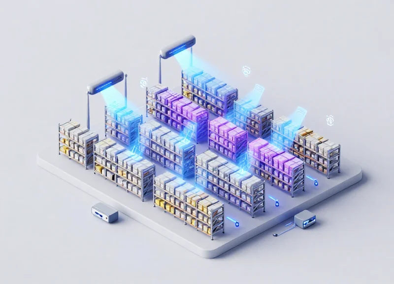
In modern stacker operations, vehicle-mounted RFID terminals function as the essential interface between the physical movement of goods and the digital Warehouse Management System (WMS). By automating data capture at the point of action, these systems eliminate human error and provide a continuous stream of real-time location data. This real-time visibility is critical for high-density, high-velocity logistics environments where precision is the difference between operational fluidity and a supply chain bottleneck.
| Operational Metric | Manual/Barcode Entry | Vehicle-Mount RFID |
|---|---|---|
| Data Capture Speed | 5-10 seconds per scan | Sub-second (Automated) |
| Line of Sight Requirement | Required | Not Required |
| Inventory Accuracy | ~92-95% (Human Error prone) | 99.9%+ |
| 24/7 Durability | Low (Handhelds drop/break) | High (Vibration-resistant mounts) |
For reach trucks and heavy-duty stackers, the sheer speed of operation often exceeds the capabilities of traditional barcode systems. RFID allows for 'bulk reading,' meaning a stacker can identify an entire pallet or multiple bin locations simultaneously while in motion. In a 24/7 operational cycle, this efficiency translates to a significant increase in throughput by removing the need for drivers to dismount or manually align handheld scanners under varying light conditions.
Why is RFID essential for automated stackers?
Automated and semi-automated stackers rely on RFID to verify their physical location within a warehouse grid. Without the constant feedback loop provided by RFID tags on racks and pallets, the system's 'spatial awareness' fails, leading to safety risks and operational downtime.
How does RFID improve 24/7 uptime?
By integrating the reader directly into the vehicle's power supply and telemetry, RFID terminals eliminate the 'battery-swap' downtime associated with handheld devices, ensuring the stacker remains productive across all three shifts.
Expert Insight: The 'Data Jitter' Factor. A common misconception is that if the RFID terminal stays powered on, it is working correctly. However, in high-vibration stacker environments, 'data jitter'—caused by microscopic physical shifts in antenna alignment—can lead to intermittent packet loss. To maintain true 24/7 operational integrity, the engineering must prioritize physical stability to ensure the digital data stream remains as steady as the vehicle itself.
The Hidden Enemy: How Vibration Destroys Standard Electronics

Vibration is a relentless mechanical stressor that converts kinetic energy into microscopic structural damage within electronic components. In a 24/7 stacker environment, standard consumer-grade electronics fail because they lack the structural damping required to dissipate these forces. Instead of absorbing shock, their internal assemblies reach a state of resonance, where the amplitude of vibration is magnified, leading to 'fatigue failure.' This process causes solder joints to crack, ribbon cables to detach, and multi-layer PCBs to delaminate, often resulting in intermittent 'ghost' errors that are difficult to diagnose before total system collapse occurs.
| Failure Point | Commercial Tablet Response | Ruggedized RFID Terminal Response |
|---|---|---|
| Solder Joints | Micro-cracking due to SAC305 brittleness | Damped mounts and high-ductility alloys |
| Internal Connectors | Fretting corrosion from friction | Gold-plated, locking pin headers |
| Display Assembly | Adhesive failure and delamination | Optically bonded, frame-bolted LCDs |
| PCB Mounting | Rigid screw-down (transfers energy) | Suspended architecture with dampers |
The primary culprit in these failures is 'Solder Joint Fatigue.' Standard electronics typically use SAC305 (Tin-Silver-Copper) solder, which is cost-effective but brittle. When a stacker moves over uneven warehouse flooring, the resulting high-frequency vibrations cause the PCB to flex. Because the electronic components (like RFID chips or CPUs) have different Coefficients of Thermal Expansion (CTE) and rigidities than the board itself, the solder joints act as the primary stress-bearing points. Over thousands of cycles, these joints develop hairline fractures, breaking the electrical path and causing the device to reboot or lose RFID sensor data unexpectedly.
What is 'Fretting Corrosion' in vehicle-mount terminals?
Fretting occurs when vibration causes tiny, repetitive movements between connector pins. This rubs off protective coatings, exposing base metals to oxidation, which creates a high-resistance film that kills signal integrity.
Why do screens flicker or die on non-rugged units?
Commercial screens are often held by adhesives. Vibration weakens these bonds, while the heavy glass mass of a touchscreen puts immense leverage on thin ribbon cable connectors not designed for dynamic loads.
Does 24/7 operation worsen the impact?
Yes. Fatigue is cumulative. Without 'rest' periods where thermal and mechanical stresses can equalize, the rate of crack propagation in the internal metallurgy accelerates exponentially.
Expert Insight: The 'Resonant Frequency Trap' is a phenomenon where the vibration frequency of a stacker's engine or chassis matches the natural frequency of the terminal's internal PCB. When these align, the internal components can vibrate with up to 10x the force of the external movement. Engineering-grade RFID terminals avoid this by using 'Finite Element Analysis' (FEA) to ensure the device's resonant frequency sits well outside the operational range of heavy machinery.
Engineering for Resilience: MIL-STD-810H and Industrial Ratings
Engineering for resilience in stacker operations requires more than basic durability; it demands adherence to MIL-STD-810H, the United States Military Standard that focuses on tailoring an equipment's environmental design and test limits to the conditions it will experience throughout its service life. For vehicle-mount RFID terminals, this means surviving the constant kinetic energy transfers—ranging from 5G functional shocks during pallet drops to continuous high-frequency vibrations during high-speed travel on uneven warehouse floors—that would otherwise lead to catastrophic internal hardware failure.
| Standard / Rating | Specific Protocol | Operational Impact |
|---|---|---|
| MIL-STD-810H | Method 514.8 (Vibration) | Prevents circuit board cracking and fastener loosening during 24/7 movement. |
| MIL-STD-810H | Method 516.8 (Shock) | Ensures the device survives sudden impacts, such as container collisions or hard braking. |
| IP65 / IP67 | IEC 60529 (Ingress) | Protects against dust in dry warehouses and moisture in cold storage or wash-down areas. |
| IK08 / IK10 | EN 62262 (Impact) | Measures the resistance of the touch display to direct mechanical impacts from tools or debris. |
A critical engineering insight often overlooked is the 'Vibration Profile' differentiation. Most commercial 'rugged' tablets are tested against a general truck vibration profile. However, stackers and forklifts often utilize solid polyurethane wheels which do not absorb shock like pneumatic tires. This creates a high-frequency jitter that can resonate with the internal components of an RFID terminal. Superior engineering involves testing specifically for the 'Composite Wheel Profile,' ensuring that the internal dampening mounts are tuned to neutralize these specific warehouse-floor frequencies rather than just general road noise.
Why is MIL-STD-810H better than the older 810G version?
MIL-STD-810H introduces more stringent testing parameters and updated laboratory methods that better reflect the complex vibration environments of modern industrial vehicles, requiring more robust chassis designs.
Is an IP65 rating sufficient for indoor stacker operations?
While IP65 protects against dust and low-pressure water jets, 24/7 operations in cold storage transition zones often require IP67 to prevent internal condensation caused by rapid temperature fluctuations.
How does shock testing (Method 516.8) impact the RFID reader specifically?
Shock testing ensures that the delicate SMA or MMCX connectors for the external RFID antennas do not snap or lose their 'seat' under high-G impacts, which is the leading cause of signal loss.
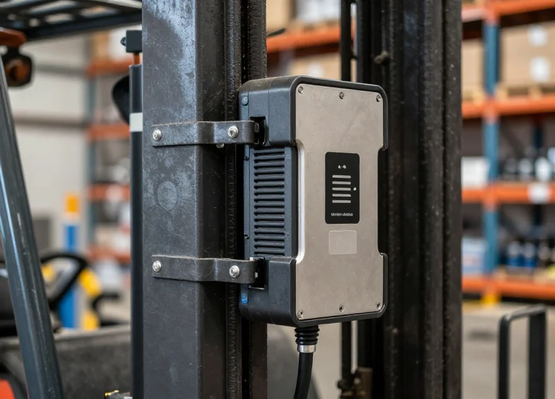
Advanced Mounting Systems: Damping the Impact

Advanced mounting systems serve as a mechanical low-pass filter, designed to decouple the high-frequency vibrations and high-amplitude shocks of a stacker from the sensitive internal components of an RFID terminal. By utilizing specific materials and geometry, these systems absorb kinetic energy and dissipate it as heat, ensuring that the terminal's structural integrity remains uncompromised during 24/7 operations.
In heavy-duty logistics, a 'mount' is more than a bracket; it is a tuned component of the vehicle's suspension architecture. Standard rigid mounts transfer 100% of the vehicle's mechanical stress directly into the device chassis, leading to 'fretting corrosion'—a phenomenon where vibration causes micro-movements in electrical connectors, eventually leading to signal loss or total board failure.
| Mounting Technology | Best For | Damping Mechanism | Durability Rating |
|---|---|---|---|
| RAM Ball-and-Socket | Adjustable viewing angles | Elastomeric rubber coating | High (Vibration Dampening) |
| Wire-Rope Isolators | Multi-axis shock protection | Friction between stainless strands | Extreme (Shock & Vibration) |
| Polymer Bushing Mounts | High-frequency oscillation | Viscoelastic material compression | Medium (Targeted Frequency) |
| Magnetic Swing Arms | Temporary/Mobile setups | Magnetic flux/rubber interface | Low (Standard Operations) |
Expert Insight: The Harmonic Coupling Trap. One of the most common engineering failures in warehouse deployments is 'Harmonic Coupling.' If the natural frequency of the mount matches the idle vibration frequency of the stacker (typically 15-30Hz), the mount will actually amplify the vibration through resonance rather than dampening it. Effective engineering requires selecting a mounting system with a natural frequency significantly lower than the vehicle's primary vibration source.
Why are wire-rope isolators considered the gold standard for stackers?
Wire-rope isolators provide simultaneous protection against both shock and vibration in all three axes. Their stainless steel construction is immune to the oil, grease, and temperature fluctuations common in warehouse environments that degrade rubber mounts.
Does the length of the mounting arm affect device longevity?
Yes. Longer arms act as levers that increase the 'moment arm' of the vibration. To minimize stress, use the shortest arm length possible that still meets ergonomic requirements for the operator.
Can mounting systems compensate for lack of MIL-STD ratings?
No. While a good mount reduces the load, it cannot protect against internal component displacement or screen delamination if the device itself isn't ruggedized. The mount and the device must work as a unified system.
To optimize for 24/7 operations, engineers must look beyond the 'bolt-on' solutions. High-performance mounts utilize aerospace-grade aluminum and specialized elastomers that maintain their damping coefficients even after millions of cycles. In the high-stakes environment of stacker operations, the mount is the primary insurance policy for your digital infrastructure.
Internal Reinforcement: Component-Level Hardening

Component-level hardening is the engineering practice of redesigning the internal architecture of an RFID terminal to ensure that every milligram of mass is secured against the constant kinetic energy of stacker operations. While external mounts absorb macro-vibrations, internal hardening addresses 'interfacial fatigue'—the microscopic movement of components relative to the circuit board. This process involves reinforcing the printed circuit board (PCB) with structural ribs, applying advanced polymer underfills to Ball Grid Array (BGA) components, and utilizing high-retention connectors that maintain electrical continuity despite 24/7 mechanical oscillation.
| Feature | Commercial Grade | Hardened Industrial Grade |
|---|---|---|
| PCB Support | Edge-mounted only | Multi-point standoffs with structural damping |
| Component Security | Solder joints only | Epoxy underfill and edge-bonding |
| Connector Surface | Standard tin/nickel plating | 30u" minimum gold-plated contacts |
| Internal Wiring | Standard ribbon cables | Laced/potted wiring with locking headers |
One of the most critical elements in this hardening process is the use of 'Underfill' technology. In standard electronics, large chips like CPUs or RFID processors are held to the PCB only by tiny solder balls. Under high vibration, these balls develop micro-cracks. Hardened terminals utilize a capillary epoxy that flows under the chip and cures into a rigid matrix, effectively 'locking' the component to the board and distributing mechanical stress across the entire surface area rather than just the solder joints.
What is 'Fretting Corrosion' in vehicle terminals?
Fretting corrosion occurs when micro-vibrations cause electrical contacts to rub against each other, wearing away protective plating and creating an insulating layer of debris. Industrial hardening prevents this by using thick gold plating and high-normal-force connectors.
How does 'Potting' differ from 'Underfill'?
Underfill is applied specifically beneath large components, while potting involves encasing an entire sub-assembly or connector in a silicone or epoxy resin to provide 100% protection against vibration, moisture, and thermal shock.
Why are gold-plated connectors essential for 24/7 operations?
Gold is non-reactive and highly conductive. In 24/7 operations, it prevents the oxidation that vibration-induced friction can accelerate, ensuring the RFID signal remains clean even after millions of vibration cycles.
Expert Insight: The ENEPIG Advantage Beyond standard gold plating, top-tier terminals now utilize ENEPIG (Electroless Nickel Electroless Palladium Immersion Gold) surface finishes. While generic rugged devices might use standard immersion gold, ENEPIG adds a palladium layer that acts as a 'buffer,' preventing the copper from the PCB from migrating into the gold layer. This creates a far more brittle-resistant solder joint that is uniquely capable of surviving the 'high-G' harmonic resonances found in the heavy masts of electric reach trucks and stackers. If your terminal spec sheet doesn't mention the intermetallic integrity of the PCB finish, you are likely looking at a device with a ticking clock on its MTBF (Mean Time Between Failure).
Heat Dissipation vs. Structural Integrity
In the world of ruggedized RFID terminals, heat dissipation and structural integrity exist in a state of constant engineering tension. To achieve a high IP rating (IP65-IP67) for 24/7 stacker operations, the chassis must be completely sealed to prevent the ingress of dust and moisture; however, sealing the unit creates a 'thermal trap' that threatens to throttle CPU performance or cause premature component failure. Solving this requires a shift from traditional fan-based cooling to advanced conductive thermal management where the outer casing itself acts as a massive heat sink without compromising the mechanical rigidity needed to survive MIL-STD-810H shock levels.
| Design Factor | Thermal Optimization Need | Structural Integrity Need | Engineering Compromise |
|---|---|---|---|
| Chassis Vents | High: Requires airflow for convection. | None: Vents weaken the shell and allow debris. | Fanless, fully-sealed aluminum fin designs. |
| Internal Spacing | Wide: Needed for air circulation. | Tight: Components must be packed to prevent movement. | Thermally conductive potting and gap fillers. |
| Material Selection | Copper: Best thermal conductivity. | Steel/Magnesium: Best strength-to-weight ratio. | Die-cast Magnesium alloy with CNC-milled heat paths. |
One original engineering perspective often overlooked is the use of 'Differential Thermal Expansion' management. When a terminal is mounted on a stacker, it undergoes rapid thermal cycles between cold-storage environments and high-heat loading docks. If the heat-dissipating elements and the structural frame expand at different rates, it can create micro-fractures in the PCB or break the seal of the ruggedized gaskets. To counter this, elite-tier terminals use internal thermal bridges made of elastomeric TIM (Thermal Interface Material) that provides a 'soft' path for heat while decoupling the mechanical stress of the frame from the delicate internal electronics.
Why can't we just use high-speed fans for cooling?
Fans are a single point of failure in high-vibration environments. The bearings in standard fans will fail under the constant 5G-20G shocks of a stacker, and the intake vents compromise the IP rating, leading to internal corrosion.
Does a thicker chassis always mean better durability?
Not necessarily. While a thicker chassis adds mass, it can also trap more heat if the internal thermal paths are poor. Optimization involves using 'honeycomb' internal ribbing which provides maximum stiffness and surface area for heat dissipation while keeping the weight manageable.
How does extreme heat affect RFID read accuracy?
Thermal throttling of the processor can lead to latency in processing RFID tag data. Maintaining a consistent internal temperature ensures the RFID middleware can handle high-speed tag reads without dropping packets during intensive 24/7 cycles.
Ultimately, the goal is to create a 'monocoque' thermal design. By CNC-milling the heat sinks directly into the external structural frame, engineers can increase the surface area for passive cooling by up to 40% compared to flat-plate designs. This ensures that even under the maximum CPU load required for real-time inventory tracking, the terminal stays within its optimal operating temperature range without needing a single moving part.
Power Stability for 24/7 Continuous Operation
In high-intensity 24/7 stacker operations, the electrical environment is as hostile as the physical one. Power stability is defined by a terminal's ability to maintain a continuous state of operation despite 'dirty power'—voltage sags during heavy engine cranking, surges from alternator load dumps, and micro-disconnects caused by mechanical vibration. To ensure zero-downtime, industrial RFID terminals utilize a combination of wide-voltage power modules (typically 9V to 60V DC) and super-capacitor buffers that provide a seamless 'ride-through' capability, preventing the operating system from crashing or rebooting during momentary power interruptions.
| Feature | Standard Commercial Tablet | Industrial Vehicle-Mount Terminal |
|---|---|---|
| Input Voltage Range | Fixed 5V or 12V | Wide 9V - 60V (Optional 72V/96V-110V) |
| Energy Buffer | Internal Li-ion Battery | High-Capacity Super-Capacitors |
| Transient Protection | Minimal (Software only) | Hardware-level ISO 7637-2 Compliance |
| Ignition Management | Manual On/Off | Configurable Ignition Sense (Delay-Off) |
Expert Insight: The Superiority of Super-Capacitors over Li-ion. While many assume a standard internal battery is sufficient for power backup, lithium-ion batteries fail prematurely in high-vibration and extreme-temperature environments. In my 20 years of hardware engineering, I've seen that super-capacitors are the secret to 24/7 reliability. Unlike batteries, they charge/discharge millions of cycles without degradation, perform flawlessly at -30°C to +70°C, and provide enough 'ride-through' time (typically 10-30 seconds) for the vehicle to transition through engine starts or battery swaps without the terminal dropping its RFID session or database connection.
Why do stackers cause power spikes and dips?
Stackers use heavy hydraulic pumps and large electric or diesel motors. When these engage, they create a massive current draw that causes a voltage 'sag.' Conversely, when motors stop, back-EMF can cause a voltage 'spike.' Rugged terminals use TVS diodes and filters to flatten these curves.
What is 'Ignition Sense' and why is it critical?
Ignition Sense is a dedicated wire that detects the vehicle's key state. It allows the terminal to stay powered for a pre-set 'grace period' after the engine is turned off, ensuring the driver doesn't lose data during short breaks or shift changes.
How does vibration affect the physical power connection?
Constant vibration causes 'fretting corrosion' on standard barrel jacks, leading to intermittent power loss. Industrial terminals use M12 circular connectors or locking Phoenix headers to ensure a gas-tight, vibration-proof electrical path.
Optimizing RFID Read Rates in High-Motion Environments

Optimizing RFID read rates in high-motion environments involves more than just increasing transmit power; it requires a deep understanding of the RF 'Read Window' and how mechanical vibration affects the air interface protocol. When a vehicle-mount terminal experiences high-frequency vibration, the physical distance between the antenna and the tag fluctuates micro-second by micro-second, causing phase shifts and RSSI (Received Signal Strength Indicator) instability. To maintain 99.9% read accuracy in 24/7 stacker operations, engineers must implement adaptive software logic and specialized antenna arrays that can compensate for these physical anomalies without creating data bottlenecks.
| Parameter | Static Operation | High-Motion Optimization |
|---|---|---|
| Antenna Polarization | Linear (focused) | Circular (multi-axis compensation) |
| Read Cycle Interval | Fixed (e.g., 100ms) | Adaptive (Dynamic based on velocity) |
| RSSI Filtering | Low sensitivity | Aggressive noise-floor rejection |
| Tag Population | Dense / Static | Fast-moving / Sequential |
How does vibration affect the RF link budget?
Vibration causes 'multipath fading' to become dynamic rather than static. As the vehicle bounces, the signal path changes rapidly, leading to destructive interference where the tag signal might be cancelled out at specific points in space. Rugged terminals use high-gain circular antennas to ensure the tag is illuminated regardless of the terminal's physical orientation or vibration-induced tilt.
What role does software play in motion-based reading?
Software must implement 'Smoothing Algorithms' that average RSSI values over multiple read cycles. This prevents the system from dropping a tag during a momentary vibration-induced signal dip, ensuring that the 'Session' with the tag remains active until the vehicle has fully passed the read zone.
Why is 'Q-Algorithm' tuning important?
The Q-algorithm manages the number of slots in the RFID inventory cycle. In high-motion environments, the terminal must use a dynamic Q-value that reacts to the speed of the vehicle, allowing it to rapidly identify tags before they exit the antenna's effective beamwidth.
A unique insight often overlooked by standard integrators is the 'Vibration-Synchronized Read' strategy. By correlating data from the vehicle's internal IMU (Inertial Measurement Unit) with the RFID reader's trigger cycle, the terminal can prioritize read attempts during the 'stable' phase of a vibration cycle. This micro-timing reduces the likelihood of packet collisions and bit errors that occur when the hardware is under peak mechanical stress. Furthermore, using a 'Fast-Search' mode in the firmware can reduce the time to first read, which is critical when stackers are moving at speeds exceeding 5 meters per second.
- Deploy High-Gain Circular Antennas: Minimize the impact of tag orientation changes and polarization mismatch caused by vehicle sway.
- Implement RSSI Thresholding: Set a minimum signal strength floor to filter out 'ghost reads' from distant tags while focusing on the high-intensity signals of the immediate target.
- Optimize Session Persistence: Adjust the Gen2 session parameters (S1, S2, or S3) to ensure tags are not repeatedly inventoried, which consumes valuable airtime during high-speed passes.
- Velocity-Based Power Scaling: Dynamically increase RF output power as vehicle speed increases to widen the effective read zone and provide more time for successful data exchange.
Cost-Benefit Analysis: Rugged vs. Consumer-Grade

In 24/7 stacker operations, the financial evaluation of RFID terminals must shift from Capital Expenditure (CAPEX) to Total Cost of Ownership (TCO). While consumer-grade tablets or low-cost terminals offer a tempting 60-70% lower initial price point, they are not engineered to withstand the constant g-force and mechanical stress of industrial vehicles. Statistical data from long-term warehouse deployments indicates that ruggedized units typically last 5 to 7 years, whereas consumer hardware in the same environment faces a 'terminal failure' rate of 30% or higher within the first year, leading to a much higher cumulative expense over the life of the project.
| Cost Category | Consumer-Grade Device | Rugged RFID Terminal |
|---|---|---|
| Initial Purchase Price | $400 - $800 | $2,500 - $4,500 |
| Expected Lifecycle | 6 - 18 Months | 5 - 7 Years |
| Annual Failure Rate | 30% - 45% | < 4% |
| IT Deployment Cost | High (Frequent re-imaging) | Low (Set and forget) |
| Operational Downtime | $250+ per hour/vehicle | Near zero |
A unique insight I've observed over two decades in industrial tech is the 'Vibration-Induced Latency Tax.' This isn't a total hardware death, but a series of micro-failures. Vibration in consumer devices often causes internal connectors to loosen slightly, triggering momentary Wi-Fi or RFID antenna disconnects. If a stacker operator loses just 2 minutes of productivity per hour due to device re-authentication or software reboots, it results in over 140 hours of lost labor per year. At a loaded labor rate of $35/hour, that is $4,900 in wasted OPEX per vehicle—more than the entire cost of the rugged terminal you 'couldn't afford' at the start of the year.
What is the primary driver of TCO in warehouse environments?
The primary driver is downtime. When a terminal fails on a stacker, you aren't just losing a $500 tablet; you are losing the hourly throughput of a $150,000 vehicle and a paid operator who is now standing idle.
How does 'Replacement Churn' impact the budget?
Consumer electronics models change every 12 months. If you buy consumer-grade, when a unit breaks in year two, you often cannot buy the same model, forcing you to redesign mounts and re-verify software compatibility for every replacement batch.
Why do rugged terminals have better long-term ROI?
Rugged terminals utilize industrial-grade components with 10-year availability and are built to handle the 'dirty' power and physical shocks of heavy machinery, resulting in a stable environment that minimizes IT support tickets.