In high-security environments, every second counts. Traditional manual checks or low-frequency proximity cards often create bottlenecks, leading to security risks or operational delays. Ultra-High Frequency (UHF) RFID gateways offer a hands-free, high-speed solution for restricted area authorization. However, achieving 99.9% accuracy within a 2-second window requires more than just installation—it demands precise configuration. This guide explores how to optimize your RFID hardware, software, and environment to ensure seamless, secure access every time, leveraging the full potential of DragonGuardGroup technology.
Understanding the Architecture of UHF RFID Gateways

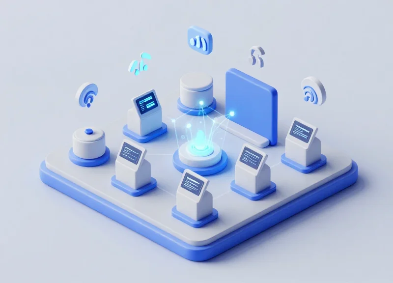
A UHF RFID gateway architecture is a synchronized ecosystem comprising high-performance fixed readers, specialized antennas, and low-latency middleware designed to identify, validate, and authorize movement within milliseconds. Unlike standard handheld scanners, gateway architecture is built for hands-free, high-throughput environments where the system must distinguish between a person intending to enter a restricted zone and a bystander merely walking past. To achieve 99.9% accuracy, the architecture relies on a 'Physical-to-Digital' bridge that processes signal strength (RSSI), phase angle, and read counts in real-time.
| Component | Primary Function | Critical Metric for 99.9% Accuracy |
|---|---|---|
| UHF Fixed Reader | The 'brain' that modulates and demodulates RF signals. | Receiver sensitivity (-80dBm or better) |
| Circular-Polarized Antennas | Converts electrical signals into electromagnetic waves. | Axial ratio and beamwidth control |
| Edge Middleware | Filters 'noise' and duplicate tag reads. | Processing latency (<50ms) |
| GPIO Interface | Triggers physical locks or visual indicators. | Switching speed and reliability |
Expert Insight: The Polarization Secret. Most failed deployments ignore the 'Polarization Match.' For restricted areas where badges can be tilted or obscured, using circular-polarized antennas is non-negotiable. While linear antennas offer more range, circular antennas ensure the signal 'corkscrews' through space, catching tags at any orientation. This architectural choice alone often accounts for the jump from 90% to 99.9% reliability in real-world movement scenarios.
- Signal Emission: The reader sends a pulse through the antennas, creating a targeted interrogation zone.
- Backscatter Energy Transfer: Passive tags harvest this RF energy to power their microchip and reflect a modified signal back.
- RSSI Filtering: The middleware analyzes Received Signal Strength Indicator (RSSI) levels to ensure only tags within the immediate 'threshold' of the door are processed.
- Database Validation: The filtered ID is cross-referenced with the Access Control List (ACL) via a high-speed API call.
What is the ideal antenna placement for a 2-second entry?
Antennas should be placed in a 'portal' configuration—one on each side of the entry point, angled at 30 degrees toward the approaching user to maximize the read window.
Why is middleware necessary for restricted areas?
Without middleware, a reader might 'over-read' tags from 30 feet away, leading to false positives and unauthorized door triggers.
Can PoE power these gateways?
Yes, high-power PoE+ (802.3at) is recommended to ensure the reader maintains maximum transmit power for deep penetration through clothing or bags.
Strategic Antenna Placement for Zero Dead Zones

Strategic antenna placement for UHF RFID gateways is the process of engineering a 'Read Zone Curtain' where RF energy is concentrated precisely at the access threshold. To ensure 99.9% accuracy within a 2-second window, antennas must be positioned to account for the 'Null Zone'—the physical space where signal phase cancellation occurs. This is achieved by utilizing circular polarized antennas mounted at a height of 7 to 9 feet, tilted downward at a 30 to 45-degree angle to create an overlapping interrogation field that captures tags regardless of their orientation or the speed of the entrant.
| Parameter | Optimal Configuration | Impact on Accuracy |
|---|---|---|
| Mounting Height | 2.1m - 2.7m (7 - 9 ft) | Reduces floor reflections and multipath interference. |
| Downward Tilt | 30° to 45° | Focuses gain on the 'strike zone' where tags are worn. |
| Antenna Type | Circular Polarized (9dBic+) | Ensures 360-degree tag orientation readability. |
| Beam Width | 60° to 75° (Horizontal/Vertical) | Defines the depth of the detection field for high-speed transit. |
Expert Insight: The 'X-Pattern' Polarization Technique. Most integrators align antennas parallel to each other. However, to achieve near-perfect accuracy in high-security zones, use an 'X-Pattern' offset. By rotating one antenna 90 degrees relative to its counterpart on the opposite side of the gateway, you effectively eliminate the linear polarization mismatch that occurs when tags are skewed. This creates a spatial diversity effect that forces the tag to respond to at least one primary wave front, even if the user is shielding the tag with their body.
- Identify the Threshold Plane: Mark the exact floor line where the authorization must occur. The 'curtain' should peak 0.5 meters before this line to allow for the 2-second processing buffer.
- Set Side-Wall Geometry: Place antennas at least 1.2 meters apart. If the corridor is wider, add a third overhead 'patch' antenna to fill the central gap.
- Adjust for Fresnel Zone Clearance: Ensure there are no metal obstructions within 1 meter of the antenna face to prevent signal diffraction and ghost reads.
- Conduct RSSI Mapping: Use a signal analyzer to ensure the Received Signal Strength Indicator (RSSI) is consistent across the entire 3D volume of the doorway.
What is the biggest cause of 'Dead Zones' in RFID gateways?
The primary cause is destructive interference from metal door frames or 'multipath' reflections from polished concrete floors, which can be mitigated by using RF-absorbent foam behind the antenna.
Can I use linear antennas for higher gain?
While linear antennas have longer range, they are highly sensitive to tag orientation. For authorization zones where tags move in unpredictable planes, circular polarization is required for 99.9% reliability.
Does person-to-person shadowing affect placement?
Yes. If two people enter simultaneously, one may 'shadow' the other. Strategic placement involves mounting antennas high enough to look down over the shoulder of the lead person to the tag of the follower.
Optimizing Reader Power and Sensitivity Settings

Optimizing UHF RFID reader power and sensitivity is the process of defining a precise 'RF bubble' where authorization occurs, ensuring that tags are read within 2 seconds while preventing 'cross-reads' from nearby unauthorized zones. For restricted area gateways, the goal is to set the Transmit Power (Tx) high enough to penetrate clothing or badges, while tightening the Receive Sensitivity (Rx) threshold to ignore tags outside the immediate entry threshold.
| Environment Type | Recommended Transmit Power (dBm) | Receive Sensitivity Threshold (dBm) | Target Read Range |
|---|---|---|---|
| Wide Industrial Gate | 28 - 30 dBm | -70 dBm | 3 - 5 Meters |
| Narrow Office Doorway | 20 - 24 dBm | -60 dBm | 1 - 2 Meters |
| High-Density Hallway | 18 - 22 dBm | -55 dBm | Under 1.5 Meters |
Expert Insight: The 'Inverse Sensitivity' Rule. Most technicians mistakenly attempt to solve read failures by simply increasing Transmit Power. However, in restricted areas, high power often causes 'RF flooding,' where signals bounce off metal lockers or concrete walls, reading tags from people just walking past the door. The professional approach is to use higher-gain antennas but lower the reader's Receive Sensitivity (RSSI filter). By telling the reader to ignore any signal weaker than -60 dBm, you effectively 'crop' the read zone to the physical doorway, ensuring only those intending to enter are authorized.
- Baseline Calibration: Start with Transmit Power at 20 dBm and Receive Sensitivity at its maximum. Test the read speed of a standard badge at the center of the gateway.
- Incremental Power Scaling: Increase Tx power in 1 dBm increments until the tag is consistently read within 500ms of entering the zone.
- RSSI Boundary Mapping: Move a tag 2 meters outside the restricted zone. If the reader still 'sees' it, adjust the Receive Sensitivity (e.g., from -80 dBm to -65 dBm) until the stray signal is ignored.
- Dynamic Loading Test: Test with multiple people entering simultaneously to ensure the reader's anti-collision algorithm is handling the increased traffic without dropping power per tag.
How does 'Dwell Time' affect gateway accuracy?
Dwell time settings determine how long a tag must be absent before it's considered 'gone.' Setting this to 500ms - 1s prevents 'flickering' authorizations while keeping the gate responsive for the next user.
Why is my reader picking up tags through the wall?
UHF waves can penetrate drywall easily. This is usually caused by excessive Transmit Power. Lower your dBm settings and use a circular polarized antenna to reduce back-lobe radiation.
Can I use 'Session 2' settings for better accuracy?
Yes. Using EPC Gen2 Session 2 or 3 ensures that tags only respond once per 'inventory' cycle, which prevents a single tag from hogging the reader's bandwidth in a crowded entry point.
Tag Selection: Matching Chips and Inlays to the Environment

To achieve sub-2-second authorization, the RFID tag must be viewed as a high-performance antenna, not just a label. In restricted area security, the primary challenge is the 'Water-Bag Effect'—the human body’s tendency to absorb UHF RF energy. Selecting a tag with a high-sensitivity chip (minimum -20 dBm) and a broad-radiation inlay is critical to ensure the gateway captures the signal regardless of whether the user is running, turning, or wearing thick clothing.
| Chip/Inlay Feature | Recommended Spec | Impact on Accuracy |
|---|---|---|
| Chip Sensitivity | -22 dBm or better (e.g., Impinj Monza R6-P) | Extends read range and allows detection through dense fabrics. |
| Inlay Orientation | Omni-directional or Dual-Dipole | Ensures 99.9% capture rate regardless of badge orientation. |
| Autotune Capability | Integrated (e.g., NXP UCODE 8) | Compensates for detuning caused by proximity to skin or metal. |
| Memory Bank | 128-bit EPC minimum | Facilitates fast cryptographic handshakes for secure areas. |
Expert Insight: The Dielectric Shift Factor. Most off-the-shelf RFID tags are tuned for 'free air' performance. However, when a badge is worn against the chest, the human body acts as a parasitic element, shifting the resonant frequency of the tag away from the 902-928 MHz band. For high-security gateways, always specify 'body-compensated' inlays. These are designed to shift back into the optimal frequency range only when in proximity to human tissue, drastically reducing 'false negatives' during peak traffic.
- Determine Placement Strategy: Decide if the tag will be integrated into a PVC ID card, a lanyard, or a clip-on badge. PVC sandwiching affects the dielectric constant.
- Select High-Gain Inlays: Choose large-form factor inlays (approx. 70x14mm) for maximum aperture size, which provides the 'loudest' signal back to the gateway.
- Perform RSSI Benchmarking: Test tags at the gateway. For 99.9% accuracy, the Received Signal Strength Indicator (RSSI) should consistently stay above -60 dBm at a 2-meter distance.
Can I use standard paper RFID labels for personnel tracking?
No. Standard paper labels are easily damaged and lack the structural integrity to maintain antenna geometry when flexed, leading to rapid performance degradation.
What is the best chip for high-speed movement?
Chips with 'Auto-Tune' technology, like the NXP UCODE 8, are superior for high-speed entry because they dynamically adjust to environmental interference in milliseconds.
Do I need 'On-Metal' tags if the environment has steel doors?
Only if the tag is applied directly to a metal surface. For badges worn by people, standard high-sensitivity inlays are preferred, provided the gateway antennas are positioned to avoid multipath interference from the doors.
Configuring Middleware for Sub-2 Second Processing

In high-security RFID systems, middleware is the digital 'brain' that bridges physical hardware and access control logic. To achieve 99.9% accuracy within a 2-second window, the software layer must move beyond simple data relaying to intelligent event processing. The primary bottleneck in authorization is rarely the speed of light; it is the latency introduced by redundant tag reads, unoptimized database queries, and round-trip delays to cloud servers. By implementing an edge-first architecture, you ensure that the decision-making logic resides as close to the UHF gateway as possible, minimizing the time between a tag entering the field and the physical lock releasing.
| Architecture Type | Average Latency | Reliability Factor | Best Use Case |
|---|---|---|---|
| Cloud-Only Processing | 800ms - 2500ms | Variable (Network Dependent) | Non-critical asset tracking |
| Hybrid (Cloud/Edge) | 200ms - 500ms | High | Standard office access control |
| Pure Edge Logic | 15ms - 50ms | Highest (Offline capable) | High-throughput restricted zones |
- Implement Sliding Window De-duplication: Configure middleware to group raw tag reads into a 'sliding window' (e.g., 200ms). Instead of processing 50 identical reads from one person walking through, the middleware treats them as a single 'event,' drastically reducing CPU load.
- RSSI-Based Proximity Filtering: Set a Received Signal Strength Indicator (RSSI) threshold. Middleware should discard any tag data with a signal strength below -60dBm to ignore 'ghost reads' from people standing near the door but not attempting to enter.
- Local Redis or In-Memory Caching: Store authorized EPC (Electronic Product Code) lists in a local Redis cache rather than querying a remote SQL database for every entry. This reduces lookup time from ~150ms to <2ms.
- Asynchronous Logging: Separate the authorization logic from the logging logic. Grant access immediately upon a cache hit, and push the log data to the central server on a background thread to prevent 'blocking' the entry.
{
  "filter_config": {
    "min_rssi": -55,
    "deduplication_window_ms": 250,
    "priority_lane": true
  },
  "auth_strategy": "local_cache_fallback",
  "on_success": "GPIO_PIN_1_HIGH",
  "telemetry": "async_mqtt"
}
Expert Tip: To guarantee the 2-second threshold, adopt a 'Latency Budget' approach. Allot 100ms for tag detection, 50ms for middleware filtering, 10ms for local cache lookup, and 100ms for the physical relay to trigger. This leaves a massive 1,740ms buffer for network jitter or secondary biometric checks if required.
Why is my middleware lagging even with local processing?
This is often caused by 'Tag Flooding.' If the reader sensitivity is too high, it picks up hundreds of tags from a nearby storage room. Use hardware-level masking or software filters to ignore non-employee tag prefixes.
Should I use HTTP or MQTT for gateway communication?
MQTT is superior for sub-2 second processing. Its pub/sub model and low-overhead header make it significantly faster than the request-response overhead of HTTP/REST.
What happens if the local cache goes out of sync?
Implement a 'TTL' (Time To Live) strategy where the cache refreshes every 60 seconds. In the event of a cache miss, the middleware should default to a 'fail-secure' mode or a quick cloud ping.
Mitigating Signal Interference and Multipath Effects
In high-security restricted areas, signal interference and multipath effects are the primary culprits behind false negatives and ghost reads. Multipath occurs when UHF RFID signals bounce off metallic surfaces—common in industrial entryways—creating constructive or destructive interference patterns that can 'hide' a tag from the reader. Mitigating these issues involves a combination of Frequency Hopping Spread Spectrum (FHSS) to bypass narrowband interference, physical RF shielding to contain the read zone, and software-defined filtering to distinguish genuine signals from environmental noise.
| Interference Type | Root Cause | Mitigation Strategy |
|---|---|---|
| Multipath Fading | Signals reflecting off metal walls or machinery. | Circularly polarized antennas and RF-absorptive foam. |
| Co-Channel Interference | Adjacent RFID gateways operating on the same frequency. | Enable 'Dense Reader Mode' (DRM) and LBT (Listen Before Talk). |
| Electromagnetic Noise | Heavy motors, VFDs, or wireless networks. | Shielded cabling (Cat6a FTP) and ferrite bead chokes. |
To ensure sub-2 second authorization, the reader must be configured to cycle through available frequencies rapidly. This prevents a single 'dead spot' from stalling the identification process. By utilizing the full 902-928 MHz band (in the US), the system ensures that if one channel is obstructed by a multipath null, the next hop will likely succeed.
- Implement RF Absorptive Shielding: Apply carbon-loaded foam or RF-blocking paint to metallic surfaces within 3 feet of the gateway to reduce signal bounce.
- Configure Frequency Hopping (FHSS): Set the reader to hop across at least 50 channels with a maximum dwell time of 400ms per channel to bypass localized interference.
- Activate Dense Reader Mode: Adjust the modulation scheme (e.g., Miller-4 or Miller-8 encoding) to narrow the spectral footprint of the reader, preventing it from bleeding into adjacent gateways.
Expert Insight: Beyond standard filtering, we recommend implementing 'Temporal RSSI Pattern Recognition.' Instead of just setting a Received Signal Strength Indicator (RSSI) floor, our veteran engineers look for a specific 'arc' in signal strength. A person moving through a gate creates a predictable rise and fall in RSSI. By filtering for this specific waveform, you can ignore static reflections from nearby objects and high-strength signals from tags that are simply stationary near the perimeter, ensuring only intentional entries are processed.
Does weather affect UHF RFID interference?
Yes, high humidity or rain can attenuate UHF signals. In outdoor restricted areas, increase the reader sensitivity by 1-2 dBm during inclement weather to maintain the 99.9% accuracy threshold.
Can I use lead shielding for RFID?
While lead blocks signals, it is heavy and hazardous. Modern RF-absorptive materials (ferrite polymers) are much more effective at 'swallowing' the energy rather than just reflecting it elsewhere.
Rigorous Testing and Benchmarking for 99.9% Accuracy
To guarantee 99.9% entry accuracy within a strict two-second window, administrators must move beyond simple 'read tests' and implement a formal benchmarking protocol. This involves quantifying the relationship between Received Signal Strength Indicator (RSSI) thresholds and the Mean Time to Authorize (MTTA). A successful benchmark validates that the system can consistently identify a specific tag, verify its credentials via the backend database, and trigger the physical lock mechanism before the user reaches the restricted threshold.
| Metric | Target KPI | Validation Method |
|---|---|---|
| First-Read Latency | < 300ms | Time from tag entering zone to first successful packet capture. |
| Total Authorization Cycle | < 1.8 seconds | End-to-end time: Tag detection to GPIO lock-release trigger. |
| Read Success Rate (RSR) | 99.9% | Success rate across 1,000 individual walk-through passes. |
| False Accept Rate (FAR) | 0.0% | Attempts to trigger read from tags outside the defined zone. |
- The RSSI Baseline Heatmap: Map the signal strength across the entire entry corridor. Ensure the 'Hot Zone' (where authorization occurs) maintains at least -50dBm, while the 'Cold Zone' (adjacent hallways) drops below -75dBm to prevent accidental reads.
- Multi-Tag Collision Stress Test: Have five personnel walk through the gateway simultaneously. This tests the anti-collision algorithm of the UHF Gen2 protocol and ensures the middleware doesn't bottleneck when processing multiple rapid-fire requests.
- The 'Body-Shielding' Orientation Audit: Test tag reads with the badge in various positions: front-facing, side-facing, and obscured by the body. This identifies whether your antenna circular polarization is truly compensating for human 'water-shielding' effects.
- Edge-to-Cloud Latency Ping: Measure the network round-trip time. If the local gateway takes 1.5 seconds just to reach the authorization server, you will never meet the 2-second target regardless of RFID hardware quality.
Expert Insight: Use the 'Ghost-Read' Stress Test. To truly reach 99.9% reliability, place an authorized tag just 12 inches outside the detection zone for 24 hours. If the gateway triggers even once (a 'Ghost Read'), your sensitivity is too high or your shielding is inadequate. In high-security environments, a false positive is often more dangerous than a missed read, as it indicates a lack of spatial control over the authorization perimeter.
How many test passes are needed for statistical significance?
For 99.9% confidence, we recommend a minimum of 500 controlled passes across different times of day to account for varying environmental EMI (Electro-Magnetic Interference).
What is the most common cause of benchmarking failure?
Middleware latency. Often the RFID reader identifies the tag in milliseconds, but the software layer performing the lookup against the employee database adds 1-2 seconds of delay.
Should I test with metallic objects present?
Absolutely. Conduct 'Dirty Environment' testing by having testers carry laptops or toolboxes, which can cause multi-path interference and signal nulls.
Integrating Gateways with Physical Security Infrastructure

Integrating UHF RFID gateways with physical security infrastructure is the process of linking the reader's data output to the mechanical control systems of barriers, such as turnstiles, speed gates, and electromagnetic locks. To achieve 99.9% accuracy within a 2-second window, this integration must move beyond simple 'read-and-send' logic, utilizing specialized communication protocols like OSDP or direct GPIO triggering to ensure the physical hardware responds the instant an authorized tag is validated by the middleware.
| Protocol | Data Speed | Security Level | Best Use Case |
|---|---|---|---|
| Wiegand | Low (Legacy) | Low (Vulnerable) | Basic legacy lock replacements |
| OSDP (v2.2) | Medium | High (AES-128) | Secure corporate or government facilities |
| TCP/IP / MQTT | High | Variable | IoT-heavy environments and cloud logging |
| GPIO Direct | Instantaneous | N/A (Physical) | High-speed turnstiles and industrial gates |
Expert Insight: The 'Edge-Trigger' Advantage. Most integrators make the mistake of sending RFID data to a cloud server and waiting for a 'grant access' command to return. In a high-traffic restricted area, this round-trip latency kills the 2-second target. The most robust systems use 'Edge Logic,' where the RFID gateway stores a local cache of authorized IDs. When a match is found, the gateway fires its internal General Purpose Input/Output (GPIO) relay to trigger the gate controller directly, bypassing network jitter entirely.
- Hardware Synchronization: Physically wire the RFID reader’s output relays to the 'Request to Exit' (REX) or 'External Trigger' terminals of your access control panel or barrier motor.
- Credential Mapping: Ensure the EPC (Electronic Product Code) formats in your RFID tags are translated into a bit-structure compatible with your existing security management software (e.g., 26-bit or 37-bit formats).
- Fail-Safe vs. Fail-Secure Configuration: Determine if the gate should stay locked (fail-secure) or open (fail-safe) during power or network loss, ensuring compliance with local fire codes.
- Feedback Loop Integration: Connect magnetic door contacts back to the gateway to confirm the barrier actually closed after the 2-second entry window, preventing 'tailgating' incidents.
Can I integrate RFID gateways with my existing HID or Lenel system?
Yes. Most enterprise RFID gateways support Wiegand or OSDP outputs, allowing them to appear as a standard badge reader to your existing Access Control Manager (ACM).
How do I prevent 'ghost' entries in the security log?
Use 'Debounce' settings in your gateway configuration to ensure that a single tag doesn't trigger the gate relay multiple times within the same passage event.
Is OSDP really better than Wiegand for RFID?
Absolutely. OSDP supports bi-directional communication, meaning the system can monitor the health of the RFID reader, whereas Wiegand is a one-way 'dumb' protocol susceptible to signal sniffing.
Scalability and Long-Term Maintenance Best Practices
Scalability in UHF RFID authorization systems refers to the architectural ability to maintain sub-2-second processing times and 99.9% entry accuracy while increasing the volume of personnel, entrance points, and data traffic. Long-term maintenance ensures that 'system drift'—the gradual degradation of hardware sensitivity and signal integrity—does not compromise security protocols. A truly scalable system treats RFID readers as edge devices rather than simple peripherals, offloading processing locally to ensure the central network remains responsive.
| Component | Maintenance Task | Frequency | Impact on Performance |
|---|---|---|---|
| Antenna Alignment | Visual inspection and angle verification | Quarterly | Prevents read zone dead spots |
| Middleware Database | Index optimization and log purging | Monthly | Maintains <200ms lookup speeds |
| Coaxial Cables | VSWR (Voltage Standing Wave Ratio) testing | Bi-Annually | Ensures maximum power delivery to antennas |
| Firmware | Security patching and protocol updates | As Released | Mitigates new interference and security risks |
Expert Insight: The 'Golden Tag' Calibration Method. To differentiate your maintenance strategy, implement a 'Golden Tag' protocol. Mount a high-quality reference tag at a fixed, hidden location within the read zone. Program your middleware to ping this tag daily at a set power level. If the Received Signal Strength Indicator (RSSI) value for this tag deviates by more than 3dBm, the system should trigger an automated alert. This allows you to detect hardware degradation or environmental interference before it results in a failed authorization for a real user.
- Adopt a Modular 'Edge-First' Architecture: When scaling to multiple sites, use edge gateways that process authorization locally. This prevents a single point of failure and ensures that network latency between sites doesn't exceed the 2-second processing window.
- Implement Automated Health Monitoring: Use SNMP (Simple Network Management Protocol) to monitor the heartbeat of every RFID reader. Real-time alerts for 'Reader Offline' or 'Antenna Disconnected' are critical for zero-downtime environments.
- Standardize Tag Provisioning: As personnel numbers grow, maintain a strict SKU list for chips and inlays. Introducing non-vetted tags into the ecosystem is the primary cause of sudden drops in entry accuracy.
How does database size affect authorization speed?
As the number of authorized users grows, flat-file searches slow down. Using indexed SQL databases or In-Memory Data Grids (IMDG) ensures that lookups remain instantaneous even with 100,000+ records.
Can environment changes impact accuracy over time?
Yes. New machinery, shelving, or even changes in ambient humidity can alter the RF environment. Periodic 'site re-surveys' are recommended whenever the physical layout of the restricted area changes significantly.
Is it necessary to update RFID tag hardware?
While the chips themselves are durable, the adhesive and inlay can degrade in industrial environments. A 3-to-5-year replacement cycle for employee badges is standard to maintain peak read sensitivity.