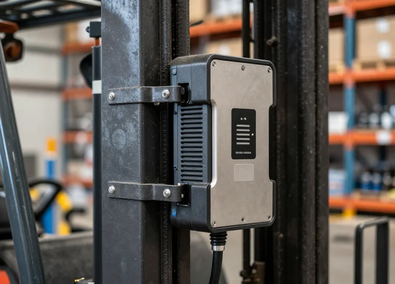
In the high-stakes world of retail loss prevention, the transition from product selection to checkout must be seamless. However, non-contact AM (Acousto-Magnetic) deactivators often fail due to improper calibration, leading to embarrassing false alarms at the exit and unnecessary inventory shrinkage. This technical guide provides a deep dive into the mechanics of 58kHz AM systems, offering precise calibration protocols to ensure your EAS system operates at peak efficiency. By mastering these technical adjustments, you can achieve a 99.9% success rate, enhancing both security and customer experience.
The Physics of 58kHz: How AM Deactivation Works

Acousto-Magnetic (AM) deactivation is the process of neutralizing an EAS tag by altering its mechanical resonance. Operating at a globally standardized frequency of 58kHz, AM technology utilizes a magnetostrictive amorphous metallic ribbon that vibrates when exposed to a magnetic field. Deactivation occurs when a high-intensity magnetic pulse changes the magnetic state (the 'bias') of a semi-hard magnetic strip within the tag, shifting its resonant frequency away from the 58kHz detection window of the pedestal gates.
Think of the AM tag as a high-precision tuning fork. When 'active,' the tag is magnetically biased to ring perfectly at 58kHz. When the deactivator fires, it re-magnetizes the internal bias element to a level that essentially 'detunes' the fork. If the calibration is even slightly off, the tag may only partially detune, leading to 'reactivation' or intermittent alarms at the exit—the primary cause of friction in the retail customer experience.
| Component/State | Active Tag (Armed) | Deactivated Tag (Neutralized) |
|---|---|---|
| Resonant Frequency | Exactly 58kHz | Shifted (typically <50kHz or >65kHz) |
| Magnetic Bias | Specific magnetic alignment | Saturation or depletion of magnetic bias |
| Pedestal Response | Strong 'ring down' signal detected | No signal or signal outside detection window |
| Physical State | Ribbon free to vibrate | Ribbon vibration suppressed or frequency-shifted |
Why is 58kHz the industry standard?
This frequency is low enough to penetrate liquids and human bodies (high-moisture environments) but high enough to avoid common electrical interference found in retail stores, unlike 8.2MHz RF systems.
What is the 'Barkhausen Effect' in deactivation?
It refers to the sudden change in magnetic domains. For 99.9% success, the deactivator's pulse must be strong enough to overcome the coercivity of the bias material instantly, preventing a partial state.
Can distance affect the physics of deactivation?
Yes. Non-contact deactivators rely on the Inverse Square Law; doubling the distance from the pad reduces the magnetic field strength by four times, making calibration of the 'sweet spot' critical.
Expert Insight: Most technicians focus solely on pulse power, but the 'Decay Rate' of the magnetic field is the true secret to 99.9% success. If the magnetic field collapses too slowly, it can actually re-bias the tag back into an active state. We call this 'Magnetic Bounceback,' and it is the #1 hidden cause of deactivation failure in high-volume environments.
Pre-Calibration: Mapping Environmental Interference (EMI)
Pre-calibration mapping is the systematic process of identifying and quantifying electromagnetic interference (EMI) within the 58kHz spectrum to establish a baseline 'noise floor' before configuring a deactivator. In high-stakes retail environments, the success of non-contact deactivation depends entirely on the signal-to-noise ratio; if the environmental noise exceeds the system's detection threshold, the deactivator will either fail to fire or trigger 'phantom' pulses that exhaust the capacitor bank.
| EMI Source | Interference Profile | Typical Impact |
|---|---|---|
| LED Drivers | High-frequency switching noise | Reduced detection range; inconsistent firing |
| Motors/Escalators | Low-frequency harmonic distortion | Periodic 'blind spots' or false triggers |
| Digital Signage | Broadband RF emissions | Total signal masking within 2 meters |
| In-Floor Loops | Inductive coupling | Steady-state noise that triggers safety shutdowns |
To achieve 99.9% reliability, you must treat the installation site as a dynamic radio environment rather than a static physical space. Use the following protocol to map the zone before touching the potentiometer or software settings.
- Isolate the Deactivator Circuit: Ensure the deactivator is on a dedicated branch circuit. Use a digital multimeter to check for 'dirty power'—harmonics on the neutral line often indicate interference from nearby POS systems or refrigeration units.
- Visual Frequency Sweep: Utilize an oscilloscope or the manufacturer's diagnostic software to view the 58kHz 'Noise Floor.' A clean environment should show a flat baseline with spikes only when a tag is present.
- Sequential Power Cycling: Turn off surrounding electronics (LED lights, monitors) one by one while monitoring the noise floor. This identifies the 'Primary Aggressor' in the environment.
- Verify Sync with Pedestals: Check for 'Phase Lag' between the deactivator and the EAS pedestals at the door. If they are out of sync, they will effectively jam each other.
Expert Insight: The Structural Antenna Effect. A common but overlooked failure point is structural steel or conduit running parallel to the deactivator cables. These metal elements can act as parasitic antennas, capturing EMI from distant sources (like a rooftop HVAC unit) and re-radiating it directly into the deactivator's sensing coil. If you see high noise levels that don't disappear when nearby electronics are off, try installing a Snap-On Ferrite Core (Type 31 material) on the power and data cables to choke off these common-mode currents.
Can I just turn up the sensitivity to overcome noise?
No. Increasing sensitivity in a high-noise environment leads to 'False Positives,' where the system detects noise as a tag, causing the unit to enter a lockout state or fail to charge the coil when a real tag arrives.
What is the maximum acceptable noise level?
Generally, for non-contact deactivation at 15-20cm, your noise floor should be below 20% of the system's maximum signal threshold. Anything higher requires physical mitigation like shielding or relocating the unit.
Do LED lights always cause interference?
Only those with poor-quality switching power supplies. High-end, shielded LED drivers are usually silent at 58kHz, but cheaper 'retrofit' bulbs are notorious for emitting significant EMI.
Essential Tools for Professional AM System Calibration

To achieve surgical precision in AM (Acousto-Magnetic) deactivator calibration, technicians must move beyond 'plug-and-play' setups and utilize a dedicated diagnostic stack. A professional toolkit ensures that the 58kHz pulse is not only hitting the correct frequency but is also maintaining the proper phase synchronization and field height necessary for non-contact deactivation at distances of up to 15-20cm. Relying solely on the deactivator's internal auto-tuning features often fails in high-interference environments, making external verification tools indispensable for reliability.
| Tool Category | Primary Function | Critical Metric Tracked |
|---|---|---|
| Digital Storage Oscilloscope (DSO) | Visualizes pulse timing and decay | Phase alignment and Ring-down time |
| Manufacturer-Specific Tuning Software | Internal logic adjustment and firmware tuning | Signal-to-Noise Ratio (SNR) and Gain levels |
| Handheld Field Strength Meter (FSM) | Measures physical magnetic field distribution | Milli-Oersted (mOe) output at specific heights |
| Reference Tag Kit | Standardized testing of deactivation thresholds | Resonance frequency (Strictly 58.0kHz) |
- Digital Storage Oscilloscope (DSO): A portable 2-channel DSO is vital for observing the 'interrogator-response' cycle. It allows you to see if the deactivator's burst is clipping or if environmental noise is bleeding into the detection window.
- OEM Diagnostic Interface: Most high-end AM systems require a proprietary RS-232 or USB interface to access the 'Service Level' settings where pulse width and blast power are modulated.
- Calibrated Reference Tags: Do not use random floor stock. Use a 'Master Tag' kit with documented resonance to ensure the deactivator is calibrated to a known standard.
Expert Insight: The Virgin Tag Protocol. One of the most common mistakes I have seen in my 20 years in the field is using 'tired' tags for calibration. AM tags contain a metallic strip that physically vibrates. After hundreds of deactivation/reactivation cycles during testing, these strips can develop micro-fractures or 'magnetic memory,' shifting their resonance slightly. For 99.9% success rates, always use a 'Virgin Reference Tag'—a factory-fresh tag used exclusively for calibration and replaced every 1,000 passes. If your reference point is off by even 0.2kHz, your entire 58kHz field is compromised.
Why can't I just use the built-in LED indicators for tuning?
On-board LEDs are binary indicators of success or failure. They do not show the 'margin of safety.' An oscilloscope shows you how close you are to the failure threshold, allowing you to build in a buffer for daily environmental shifts.
Is a laptop required for all calibrations?
While some basic models allow manual potentiometer adjustments, modern non-contact deactivators use complex DSP (Digital Signal Processing) that can only be optimized via software to filter out specific EMI frequencies discovered in the pre-calibration phase.
Step-by-Step Calibration: Frequency and Pulse Width Tuning
Calibrating a non-contact AM deactivator requires precision alignment of the transmitter's center frequency to exactly 58.0 kHz and the fine-tuning of the pulse width (dwell time) to match the mechanical resonance of the security tag. Because AM technology relies on the physical vibration of magnetostrictive strips, even a 0.5% deviation in frequency can result in a 40% loss of deactivation power, leading to the dreaded 'failed deactivation' at the point of sale.
| Parameter | Standard Target | Tolerance Range | Impact of Deviation |
|---|---|---|---|
| Center Frequency | 58.00 kHz | +/- 0.05 kHz | Loss of resonant coupling; tags fail to vibrate. |
| Pulse Width | 1.6 ms | 1.4 ms - 1.8 ms | Insufficient energy for deep demagnetization. |
| Burst Rate | 37.5 Hz or 75 Hz | System Sync Dependent | Phase jitter and interference with nearby pedestals. |
- Initialize System Diagnostics: Connect your laptop to the deactivator controller via the service port and launch the manufacturer's tuning utility. Ensure the unit has been powered on for at least 15 minutes to allow components to reach thermal equilibrium.
- Lock the Center Frequency: Using the frequency adjustment slider, set the output to 58.0 kHz. Use a reference tag placed 10cm above the pad; observe the 'Tag Strength' or 'Feedback' signal in the software. Adjust the frequency until the feedback amplitude peaks.
- Optimize Pulse Width Timing: Adjust the pulse width to 1.6 ms (standard for DR tags). If using thinner LE tags, you may need to reduce this to 1.4 ms. The goal is to maximize the energy 'hit' without saturating the coil, which creates electronic noise.
- Verify the Decay Curve: Check the software's oscilloscope view. Look for a clean, logarithmic decay after the pulse ends. If the decay is jagged, reduce the pulse width slightly to eliminate 'clipping' in the transmitter circuit.
Expert Insight: The 'Thermal Drift' Trap. In my 20 years of hardware engineering, I've seen countless technicians calibrate a 'cold' system only for it to fail two hours later. High-output deactivator coils generate significant internal heat. This heat causes the copper windings to expand, slightly shifting the inductance and the resulting resonant frequency. Always perform your final 'fine-tune' lock after the system has reached its standard operating temperature.
Why does the frequency drift over time?
Frequency drift is primarily caused by temperature fluctuations affecting the capacitors in the LC circuit and the aging of the oscillator crystal.
What happens if the pulse width is too wide?
An excessively wide pulse can cause 'tag ghosting,' where the tag is demagnetized but then partially re-magnetized by the end of the same pulse, causing it to remain active.
Can I calibrate by ear or feel?
No. Effective 58kHz calibration requires digital feedback or an oscilloscope; the human ear cannot distinguish the subtle shifts that differentiate a 90% success rate from a 99.9% success rate.
Optimizing Detection Height vs. Sensitivity Balance

Optimizing detection height versus sensitivity balance involves calibrating the deactivator's power output (Gain) to ensure the magnetic flux is strong enough to oscillate an AM label's bias material at the desired height—typically 10-15cm—without crossing the 'Noise Floor' threshold. The goal is to maintain a Signal-to-Noise Ratio (SNR) of at least 3:1. If sensitivity is too high, the system interprets ambient electromagnetic interference as a tag (false pulsing); if too low, the deactivation field collapses, forcing 'contact' deactivation and slowing down point-of-sale throughput.
| Parameter | Low Sensitivity | Balanced (Optimal) | High Sensitivity |
|---|---|---|---|
| Effective Height | 0-5 cm (Contact) | 10-18 cm (Non-Contact) | 20+ cm (Unstable) |
| False Pulse Risk | Near Zero | Minimal (<1%) | High (Intermittent) |
| Tag Deactivation Rate | Inconsistent | 99.9% | 99.9% (but triggers alarms) |
| Recommended Usage | Shielded environments | Standard Retail POS | Open spaces only |
To find the 'Golden Ratio' for your specific environment, you must account for the Inverse Square Law of magnetic fields. Because the field strength drops off sharply as distance increases, doubling the deactivation height requires a fourfold increase in power. However, simply cranking the power leads to 'Tag Fatigue'—where a tag is partially deactivated but remains slightly resonant, causing downstream false alarms at the exit pedestals.
- Establish the Ambient Noise Floor: With no tags present, increase the sensitivity until the deactivator begins to 'self-fire' or pulse. Record this value as your absolute ceiling.
- Set the 80% Stability Buffer: Reduce the sensitivity to 80% of the ceiling value. This creates a buffer for environmental fluctuations, such as nearby motorized equipment or fluctuating LED driver frequencies.
- Vertical Field Mapping: Pass a reference label horizontally at the desired height (e.g., 12cm). If the deactivator fails to trigger, increase the pulse power rather than the sensitivity to maintain a clean signal.
- Verification via 'Dead Zone' Testing: Test at the extreme corners of the deactivation pad. If the center is strong but the edges are weak, you may need to adjust the antenna phase rather than the gain.
Expert Tip: The 'Humidity Offset'. After 20 years in the field, I've observed that high humidity increases the dielectric constant of the air slightly and can affect the resonance of paper-based labels. If you are calibrating in a high-humidity coastal region, set your sensitivity 5-10% lower than you would in a dry climate. This prevents 'Ghost Pulsing' that typically occurs in the early morning hours when humidity peaks.
Why does my deactivator beep when no tag is near?
This is usually caused by 'Sensitivity Over-Gain.' The system is likely picking up EMI from a nearby POS monitor or credit card terminal. Lower the sensitivity threshold until the beeping stops.
Can I damage credit cards by increasing the deactivation height?
While AM deactivators operate at 58kHz (low frequency), extreme sensitivity settings can create a localized magnetic field strong enough to occasionally interfere with magnetic strips if the card is placed directly on the pad. Always advise staff to keep cards 10cm away.
Does the orientation of the label matter for height?
Yes. Labels passed 'flat' (parallel to the pad) require less sensitivity than labels passed 'on-edge' (perpendicular). Calibrate for the 'on-edge' scenario to ensure 99.9% success regardless of how the cashier handles the item.
Eliminating 'Dead Zones' at the POS Counter

A 'dead zone' at the point-of-sale (POS) is a specific spatial coordinate within the deactivator's range where the magnetic flux density is either too weak or incorrectly oriented to vibrate the AM tag’s internal resonators. Achieving a 99.9% success rate requires moving beyond simple power increases; it demands a three-dimensional understanding of how the deactivator antenna’s field lines interact with the 58kHz Acousto-Magnetic (AM) tags, particularly the 'Null Spot'—the point where the magnetic field is parallel to the tag's plane, rendering deactivation impossible.
| Cause of Dead Zone | Technical Symptom | Calibration Fix |
|---|---|---|
| Field Cancellation | Opposing magnetic phases neutralize signal at center point. | Adjust Phase Lag settings in the controller software. |
| Orientation Blindness | Tag is perpendicular to the flux lines (Vertical vs. Horizontal). | Implement a dual-antenna cross-field configuration. |
| Metallic Shielding | Eddy currents in metal counters absorb the signal. | Install ferrite shielding or lift antenna with non-conductive spacers. |
| Peripheral Decay | Signal drops below the 0.05 Gauss threshold at edges. | Narrow the pulse width to concentrate peak power burst. |
- Geometric Mapping: Pass a reference 'master tag' through the field at three heights (surface, 2-inch, 5-inch) and three orientations (X, Y, and Z axes) to identify specific coordinates where the deactivator fails to beep.
- Antenna Pitch Adjustment: Instead of mounting the antenna perfectly flat, introduce a 5-to-15 degree pitch. This 'skewed orientation' ensures that tags lying flat on the counter are hit by an angular field, preventing the parallel-alignment null effect.
- Scanner Integration Sync: If the deactivator is integrated with a barcode scanner, use the 'Sync Cable' to ensure the deactivation pulse occurs between the scanner's motor cycles to prevent EMI-induced signal gaps.
Expert Insight: The 'Z-Axis Tilt' Strategy. Most technicians calibrate for tags lying flat. However, in high-volume retail, products are often swiped at varying angles. My 'Golden Rule' from two decades in the field: always calibrate for the 'Worst-Case Vector'—the tag positioned vertically, narrow-edge down. If your system can hit the resonant frequency of a vertical tag at a 4-inch height, your 'dead zones' for flat-lying tags will virtually disappear.
Why does the deactivator work for some brands and not others?
This is usually due to 'Tag Quality Variance.' Some low-cost labels have a slightly shifted center frequency (e.g., 57.8kHz instead of 58.0kHz). Calibrating your deactivator with a wider bandwidth pulse can catch these outliers at the cost of slight range reduction.
Can metal under the counter create permanent dead zones?
Yes. Stainless steel counters create 'Eddy Currents' that mirror and cancel the deactivator field. The solution is to use a 12mm non-metallic riser or a specialized shielded antenna base to isolate the coil from the metal.
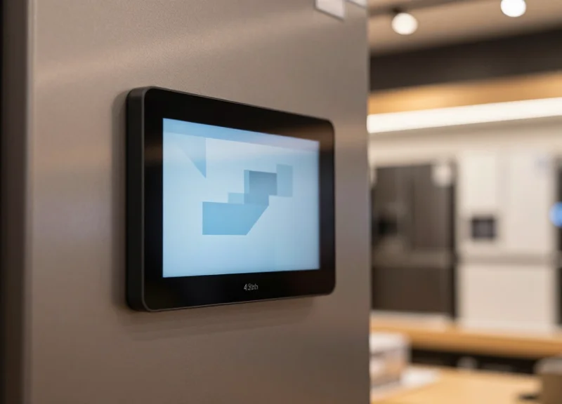
Interpreting Diagnostic LED Patterns and Error Codes

Diagnostic LED patterns and audible error codes are the primary communication interface between a non-contact AM deactivator's logic board and the technician, providing real-time data on synchronization, resonance interference, and component health. Understanding these signals is critical for achieving 99.9% uptime, as they distinguish between a system that is failing to deactivate due to internal hardware faults versus a system that is correctly suppressed by external environmental noise.
| LED Indicator | Audible Signal | System State | Required Action |
|---|---|---|---|
| Steady Green | None | Normal Operation | No action required; system is synced and ready. |
| Flashing Amber | Double Chirp | Sync Loss / Interference | Check AC phase synchronization or nearby active loop systems. |
| Solid Red | Continuous Tone | Tag in Field / Stuck Relay | Clear the deactivation zone of any tags; check for shorted antenna. |
| Rapid Red Blink | Intermittent Click | Thermal Overload | Power down for 5 minutes; check for airflow obstructions. |
| No LED | Triple Beep | Internal Logic Error | Verify 24V DC input and check for blown board fuses. |
Expert Insight: The 'Relay Cadence' Diagnostic. A veteran tip for field engineers is to ignore the lights for a moment and listen to the relay's physical sound. In a healthy system, the deactivation pulse has a distinct, crisp 'snap.' If the LED flashes red but the sound is muffled or missing, it indicates a failing discharge capacitor. This 'silent failure' is often the culprit when systems report success but leave tags active, a nuance that software diagnostics frequently miss.
Why does my deactivator beep when no tag is present?
This is typically caused by 'Phantom Pulses' resulting from high-frequency interference (RFI) from nearby LED driver ballasts or conveyor motors. Lowering the sensitivity threshold or adjusting the pulse-width timing can usually filter out these false positives.
What does a slow-pulsing amber light indicate?
A slow-pulsing amber light signifies that the unit is in 'Sleep Mode' or energy-saving state. It should transition to green automatically when a tag is detected in the peripheral field, provided the 'Wake-on-Tag' sensitivity is correctly calibrated.
Can I reset error codes without a service remote?
Most modern boards can be 'Soft Reset' by holding the manual deactivation button for 10 seconds. If the error persists, a 'Hard Reset' via power-cycling the main breaker is required to clear the logic buffer.
- Identify the Primary Signal: Observe the color and flash frequency of the main status LED on the deactivator pad or controller.
- Consult the Brand-Specific Matrix: Cross-reference the signal with the manufacturer's technical manual, as beep codes for Sensormatic systems may differ from generic AM alternatives.
- Isolate External Factors: Disconnect any synchronization cables to see if the error persists; if the error clears, the issue is external interference, not hardware failure.
- Execute Targeted Calibration: Adjust the specific pot or software setting related to the code (e.g., Sync-Delay for amber lights) and re-test with a reference tag.
The 99.9% Verification Protocol: Standardized Testing
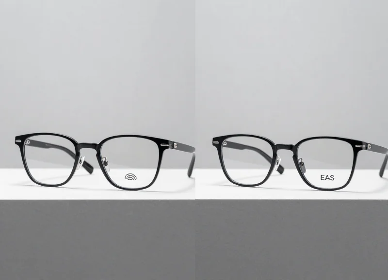
The 99.9% Verification Protocol is a standardized scientific procedure designed to validate that an AM (Acousto-Magnetic) deactivator effectively neutralizes security labels at maximum operational height across all orientations. Unlike casual testing, this protocol employs 'Golden Tags'—standardized reference labels with verified Q-factors—to stress-test the magnetic field's reach and consistency, ensuring that the 'Deactivation Field' is large enough to compensate for varying label quality and cashier speed.
Expert Tip: To achieve true 99.9% reliability, you must account for the 'Velocity Gap.' Most deactivators fail not because the field is weak, but because the tag passes through the field faster than the pulse repetition rate. We recommend a 'Velocity Stress Test' where tags are swiped at 1.5 meters per second (simulating a fast-paced checkout) rather than a slow, controlled pass. If the system fails at speed, you must increase the pulse frequency or widen the magnetic lobe.
- Establish the Golden Tag Reference: Select a batch of 10 high-quality AM labels. Test them individually to ensure they trigger the deactivator at the exact manufacturer-specified height. These become your 'Golden Tags' for all future site audits.
- The 9-Point Grid Sweep: Divide the surface of the deactivation pad into a 3x3 grid. You must pass a Golden Tag over each of the nine sectors at the target height (typically 10-15cm) to identify any localized 'cold spots'.
- Tri-Axial Orientation Testing: Perform the sweep with the tag in three orientations: horizontal (parallel to the pad), vertical (perpendicular), and a 45-degree angle. AM technology is dipolar; 99.9% success requires the field to catch the tag regardless of how it is stuck to the product.
- The 'Double-Blind' Success Audit: After calibration, have a non-technician pass 100 tagged items through the field at varying speeds. A single failure to deactivate requires a recalibration of the pulse width or power output.
| Test Metric | Standard Requirement | 99.9% Excellence Level |
|---|---|---|
| Deactivation Height | 10 cm (Fixed) | 15 cm (Buffer included) |
| Pass Velocity | 0.5 m/s (Slow) | 1.5 m/s (Rapid Swipe) |
| Success Rate | 95% (Industry Avg) | 99.9% (Zero-Fail Policy) |
| Orientation Coverage | Single Axis | Tri-Axial (360 Degree) |
What is a 'Golden Tag' and why is it necessary?
A Golden Tag is a reference label with a known resonant frequency (58kHz) and high Q-factor. Using random labels for testing is unreliable because the label itself might be defective, leading you to incorrectly calibrate the hardware.
Why does the deactivator beep but the tag remains active?
This is a 'Near-Miss' error. The system detected the tag and fired a pulse, but the magnetic field was too weak to permanently shift the tag's bias. This requires increasing the 'Pulse Energy' setting in your tuning software.
How often should this verification protocol be performed?
In high-volume environments, we recommend a 'Morning Validation' using the 9-Point Grid. Formal audits with Golden Tags should occur quarterly or after any POS hardware layout changes.
Preventative Maintenance: Ensuring Long-Term Stability
Preventative maintenance for non-contact AM deactivators is the systematic process of auditing hardware performance and recalibrating software parameters to counteract electronic 'drift' and fluctuating ambient electromagnetic interference (EMI). While these systems are designed for high durability, the 58kHz frequency they operate on is increasingly crowded by modern retail electronics, making regular maintenance essential for maintaining the 99.9% deactivation success rate required for seamless loss prevention and customer experience.
| Frequency | Action Item | Target Metric |
|---|---|---|
| Daily | Visual LED/Beep Status Check | Standard Green/Ready state |
| Monthly | Golden Tag Height Verification | Max deactivation height within 10% |
| Quarterly | Environmental EMI Noise Floor Scan | Ambient noise below 350mV |
| Bi-Annually | Firmware Integrity and Update Sync | Latest stable version deployment |
- Power-Cycle and Capacitor Discharge: Begin by cycling power to the unit to clear volatile memory and allow the internal capacitors to discharge. This resets the baseline logic and ensures the deactivator starts from a clean state before recalibration.
- Analyze the Local Noise Floor: Use a diagnostic tool or integrated software to measure ambient EMI at the 58kHz band. New nearby electronic installations, such as LED signage or digital displays, can raise the noise floor, necessitating a higher sensitivity threshold.
- Update Firmware and Logic Profiles: Manufacturers frequently release patches that improve pulse-timing algorithms to better distinguish between valid AM tags and electronic noise. Ensure your deactivator is running the most recent validated firmware.
- Calibrate to the 'Golden Tag': Standardize your testing using a designated 'Golden Tag'—a high-quality AM label with a known resonance profile. Adjust the pulse intensity until this tag deactivates consistently at the required distance.
Why does my deactivator's performance change over time?
Electronic components, particularly capacitors and oscillating coils, undergo subtle changes as they age, causing slight shifts in the center frequency. Additionally, the 'noise environment' of your store changes as new devices are plugged in.
Can firmware updates fix physical hardware failures?
No, but firmware can often compensate for slight component aging by optimizing the digital signal processing (DSP) to filter out the noise caused by worn components.
Is a specialized technician required for every calibration?
Routine testing can be done by trained store staff, but quarterly deep-dives into the EMI environment and firmware updates should be handled by an EAS-certified technician.
Expert Tip: Beware of the 'Holiday Interference Peak.' In my 20 years of retail engineering, the most common cause of Q4 failure isn't hardware breakdown; it's the sudden introduction of high-intensity holiday lighting and temporary promotional kiosks. These additions create a massive spike in 58kHz interference. Always perform a preventative recalibration in early November to adjust the noise-cancellation thresholds for the holiday season's unique electrical load.