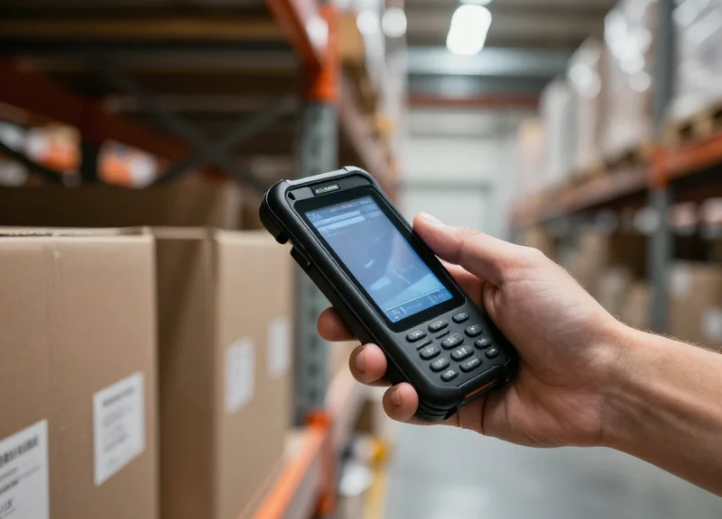
In the precision-driven world of semiconductor manufacturing, the movement and maintenance of wafer boxes (FOUPs and FOSBs) are critical to yield and operational efficiency. As fabs transition toward high-level automation and Industry 4.0, the manual tracking of these containers is no longer viable. However, the cleaning and sterilization cycles—involving extreme temperatures and corrosive chemical baths—present a significant hurdle for standard identification technology. This technical blueprint outlines the strategic integration of high-temperature RFID tags, ensuring that data integrity and asset visibility remain uncompromised even in the harshest semiconductor processing environments.
The Evolution of Wafer Traceability in Smart Fabs

The evolution of wafer traceability is defined by the transition from passive, line-of-sight optical identification, such as barcodes and QR codes, to resilient, non-line-of-sight digital signatures powered by High-Temperature RFID. In modern Smart Fabs, traceability is no longer just about identifying a batch; it is about maintaining a continuous 'digital twin' for every Front Opening Unified Pod (FOUP) as it moves through high-stress environments. Unlike traditional methods, high-temperature RFID tags are engineered to survive the extreme thermal cycles (often exceeding 150°C) and aggressive chemical exposure of automated wafer box washers, ensuring that the link between the physical wafer and its process data is never severed.
| Feature | Traditional Barcodes | High-Temp RFID | |||
|---|---|---|---|---|---|
| Read Reliability | Prone to degradation from chemicals | 99.99% read rate through steam/plastic | |||
| Line-of-Sight | Required (Manual or Robotic alignment) | Not required (Omnidirectional) | Data Integrity | Static; non-rewritable | Read/Write capable for real-time history |
| Thermal Resistance | Adhesives fail at 60°C | Specialized encapsulation survives 200°C+ |
As the industry moves toward sub-7nm process nodes, the margin for error in wafer handling has vanished. Smart Fabs require autonomous material handling systems (AMHS) that can verify the cleanliness and history of a wafer carrier before it enters a photolithography or deposition tool. If a carrier is not properly sterilized or is misidentified, the resulting contamination can scrap an entire lot of 300mm wafers. High-temperature RFID provides the ruggedized data bridge necessary to automate these validation steps without human intervention, effectively removing one of the most common vectors for yield loss.
Why are standard RFID tags insufficient for wafer cleaning?
Standard RFID tags utilize low-temperature plastics and solder that delaminate or melt when exposed to the pressurized steam and caustic surfactants used in automated wafer box washers. High-temperature variants use specialized PEEK or ceramic encapsulation to protect the IC.
What is the 'Shadow Cost of Misreads' in traceability?
In high-volume fabs, a 0.5% optical barcode failure rate—often caused by steam fogging or label peeling—forces manual overrides. My experience shows these manual touches are the primary cause of FOUP cross-contamination, which can cost a facility upwards of $500,000 in a single yield-loss event.
How does RFID support Industry 4.0 in semiconductors?
By allowing 'on-tag' data storage, RFID enables decentralized decision-making. A wafer box can communicate its own cleaning status and remaining shelf-life directly to the fab's MES (Manufacturing Execution System) without needing a central database lookup for every movement.
Decoding the Harsh Environment: Cleaning and Sterilization Challenges

The harsh environment of wafer box cleaning involves a trifecta of high-temperature thermal cycling (up to 180°C), aggressive chemical exposure (pH 1-14), and high-frequency ultrasonic cavitation. For an RFID tag to be viable in a Front Opening Unified Pod (FOUP) or specialty wafer carrier, it must maintain hermeticity and integrated circuit (IC) functionality while undergoing rapid transitions between these stressors. Failure to account for the synergistic effects of heat and moisture often leads to delamination or 'popcorning' of the RFID package, resulting in catastrophic loss of lot traceability.
| Process Stressor | Typical Parameters | Impact on Standard RFID |
|---|---|---|
| Thermal Exposure | 60°C to 180°C (Drying/Sterilization) | Memory corruption or physical chip detachment |
| Chemical Bath | SC-1 (NH4OH+H2O2), SC-2 (HCl+H2O2) | Corrosion of antenna or adhesive failure |
| Ultrasonic Cleaning | 40 kHz to 120 kHz frequencies | Fracturing of internal wire bonds or solder joints |
| Sterilization (VHP) | Vaporized Hydrogen Peroxide | Oxidization of exposed metallic contact points |
One often-overlooked challenge is the 'Thermal Expansion Mismatch'. During high-heat drying cycles, the RFID tag's encapsulation material and the wafer box (typically polycarbonate or PEEK) expand at different rates. Without advanced bonding techniques or specific expansion-coefficient matching, the tag can create micro-cracks in the box housing or detach entirely, creating a significant contamination risk in the cleanroom.
Why does ultrasonic cleaning kill standard RFID tags?
The cavitation bubbles created by ultrasonic waves generate localized high-pressure micro-jets. These jets can penetrate standard epoxy potting, eventually reaching the IC and vibrating the delicate gold or copper wire bonds until they fatigue and snap.
How do chemicals affect the RFID read range?
Aggressive cleaning agents like SC-1 can etch away at metallic antennas if the encapsulation is not 100% hermetic. Even minor oxidation of the antenna increases electrical resistance, which sharply reduces the tag's read range and reliability.
Is outgassing a concern during heat cycles?
Yes. In Class 1 cleanrooms, RFID tags made with low-grade plastics can release Volatile Organic Compounds (VOCs) when heated. Only medical-grade or semiconductor-grade polymers should be used to prevent wafer contamination.
Expert Insight: The 85/85 Test Reality. While many tags claim high-temperature resistance, they often fail the '85/85' test (85°C at 85% relative humidity) which simulates the humid drying stages of wafer box cleaning. Silicon Valley fabs now require tags that exceed these standards, often opting for ceramic or specialized PEEK-encapsulated designs that treat moisture ingress as the primary threat over pure temperature.
Material Science: Selecting High-Temperature RFID Encapsulations

In the context of wafer box cleaning, high-temperature RFID encapsulation is the science of creating a hermetic or near-hermetic barrier that shields the internal Integrated Circuit (IC) from thermal degradation and chemical ingress. While standard RFID tags use epoxy or basic polymers, wafer box environments require advanced engineering plastics like Polyether Ether Ketone (PEEK) or Polyphenylene Sulfide (PPS) to maintain structural integrity at temperatures up to 200°C and resist the corrosive nature of SC-1 and SC-2 cleaning chemistries.
| Material | Max Operating Temp | Chemical Resistance | RF Transparency | Primary Use Case |
|---|---|---|---|---|
| PEEK | 250°C | Excellent (Acids/Alkalis) | High | High-pressure sterilization and autoclave cycles. |
| PPS | 220°C | Very Good | Medium | Standard hot-water cleaning and drying cycles. |
| Ceramic | 400°C+ | Superior | Low (Requires Tuning) | Direct bonding to metallic components or extreme heat. |
| Teflon (PTFE) | 260°C | Universal | High | High-purity environments requiring zero outgassing. |
Beyond simple temperature resistance, the 'Coefficient of Thermal Expansion' (CTE) is the most overlooked factor in material selection. If the encapsulation material expands at a significantly different rate than the internal PCB or the wafer box it is attached to, micro-cracks will form at the interface. Over time, these cracks act as capillary pathways for cleaning fluids, leading to internal short-circuits and 'phantom' tag failures—where the tag works when dry but fails during the wash cycle.
Why is PEEK often preferred over PPS for wafer boxes?
While PPS is more cost-effective, PEEK offers superior mechanical toughness. In ultrasonic cleaning baths, PPS can become brittle over hundreds of cycles, whereas PEEK maintains its elasticity, preventing the housing from shattering under high-frequency vibration.
Does the encapsulation color affect performance?
In semiconductor environments, natural (unpigmented) materials are often preferred to prevent trace metal contamination. However, black laser-markable grades are common for serial number visibility; these must be tested for carbon-black interference with the RF signal.
How does moisture absorption impact RFID range?
Materials like Nylon absorb moisture, which increases their dielectric constant and detunes the antenna. PEEK and PPS have near-zero moisture absorption, ensuring the tag's resonance frequency remains stable throughout the drying phase.
Expert Insight: The CTE Matching Strategy. For maximum longevity, specify tags that utilize 'Glob-Top' potting compounds inside the PEEK shell that are specifically matched to the CTE of the FR4 substrate. By creating a gradient of thermal expansion, you eliminate the internal shear stress that typically shears the solder bumps off the RFID chip during the transition from a 180°C drying oven to a 20°C cooling station.
Integration Architecture: Mounting and Attachment Strategies

Successful integration of RFID tags into wafer box architectures requires an attachment strategy that balances structural integrity with signal transparency. The three primary methods—mechanical fastening, high-bond adhesives, and recessed molding—must account for differential thermal expansion between the tag housing and the FOUP/FOSB material (typically Polycarbonate or PEEK). Failure in this architecture often stems not from the tag's internal electronics, but from the physical separation of the tag due to shear stress during rapid temperature transitions.
| Method | Durability | Pros | Cons |
|---|---|---|---|
| Mechanical Fastening | Highest | Tamper-proof; handles extreme vibration. | Requires structural modification; potential for particle traps. |
| High-Bond Adhesive | Moderate to High | Fast application; no structural drilling needed. | Susceptible to chemical degradation and outgassing. |
| Recessed Molding | Excellent | Flush surface prevents snags; best for aerodynamics. | Requires custom carrier design; difficult to retrofit. |
Expert Insight: The CTE Mismatch Factor. A common oversight in tag integration is ignoring the Coefficient of Thermal Expansion (CTE). If a PPS-encapsulated tag is rigidly bonded to a Polycarbonate wafer box, the materials will expand at different rates during a 180°C sterilization cycle. Without a 'buffer' layer—such as a specialized silicone-based adhesive with high elongation properties—the resulting shear stress can literally snap a mechanical fastener or cause adhesive delamination. Always select an attachment medium with at least 150% elongation capability to absorb this thermal movement.
- Surface Preparation: Clean the bonding area with high-purity Isopropyl Alcohol (IPA) to remove oils and residues. For low-surface-energy plastics, a plasma treatment or specialized primer is recommended to increase surface tension.
- Adhesive Application: Apply a medical-grade, high-temperature epoxy or VHB (Very High Bond) tape specifically rated for the peak temperature of the cleaning cycle. Ensure zero air bubble entrapment to prevent 'popping' during vacuum drying stages.
- Curing and Outgassing Control: Cure the assembly in a controlled environment. For cleanroom applications, it is vital to bake the carrier post-attachment to ensure any volatile organic compounds (VOCs) are outgassed before the carrier enters the production line.
Will adhesives survive ultrasonic cleaning?
Only if they have high shear modulus and are applied to a properly etched surface. Traditional adhesives often 'cavitate' and fail during ultrasonic cycles; epoxy-based resins generally perform better here.
Can we use metal screws for mechanical fastening?
Avoid ferrous metals as they interfere with the RFID's RF field. If mechanical fastening is required, use PEEK screws or non-magnetic stainless steel (316L) while ensuring the tag is 'metal-mount' compatible.
What is the risk of recessed mounting?
The primary risk is signal attenuation if the recess is too deep or if the surrounding material contains carbon-black fillers. Testing the read-range within the specific carrier geometry is essential.
Frequency and Protocol Considerations: UHF vs. HF in the Fab
In the semiconductor fab, the choice between High Frequency (HF) and Ultra-High Frequency (UHF) RFID protocols is governed by the physical environment of the cleaning bay and the required read throughput. HF (13.56 MHz) is traditionally favored for 'Near-Field' applications where accuracy in the presence of liquids is paramount, while UHF (860-960 MHz) has become the standard for automated material handling systems (AMHS) due to its superior read range and rapid anti-collision capabilities. Determining the right frequency depends on whether the tag must be read while submerged in a cleaning chemical or while moving at high speeds on an overhead hoist transport (OHT).
| Feature | HF (ISO 15693 / 14443) | UHF (EPC Gen2 / ISO 18000-6C) |
|---|---|---|
| Typical Read Range | 2 cm to 15 cm | 1 m to 10 m |
| Performance near Liquids | Excellent; minimal signal absorption | Moderate; susceptible to detuning |
| Performance near Metals | Moderate; requires isolation spacers | Poor; requires specialized 'on-metal' design |
| Data Transfer Rate | Lower (approx. 26 kbps) | Higher (up to 640 kbps) |
| Bulk Reading | Limited (serial processing) | High (hundreds of tags per second) |
The 'Metal-Water Paradox' in wafer cleaning poses a unique challenge. While UHF offers the long-range visibility needed for inventory management, the frequency is highly sensitive to the high-dielectric constant of the fluids used in deionized (DI) water rinses and chemical baths. If a wafer box (FOUP or cassette) is being tracked through a wet bench, HF is often the more reliable choice because its magnetic coupling mechanism is less affected by the moisture and chemistry than the electromagnetic backscatter of UHF.
Can UHF tags be used in ultrasonic cleaning cycles?
Yes, but with caveats. The main risk is not the frequency itself, but the mechanical stress on the bond between the IC and the antenna. High-temperature UHF tags must be designed with 'flip-chip' or reinforced bonding to survive the cavitation forces of ultrasonic baths.
Why is ISO 15693 preferred over ISO 14443 for HF in Fabs?
ISO 15693 (Vicinity Cards) offers a longer read range (up to 1 meter with large antennas) compared to the 'Proximity' limits of ISO 14443, making it more flexible for gate-based tracking in cleanroom corridors.
Does the frequency affect the tag's thermal lifespan?
Directly, no. However, UHF chips are often smaller and more sensitive to the thermal expansion coefficients of the substrate. Ceramic UHF tags are typically more stable than PET-based HF in-lays during 200°C+ sterilization cycles.
Expert Insight: The Hybrid Approach and Circular Polarization. A common mistake in Fab integration is choosing a single frequency for the entire lifecycle. Many modern facilities utilize 'Dual-Frequency' tags or hybrid reader zones. When deploying UHF in the high-reflectivity environment of a stainless steel wet bench, always specify Circularly Polarized Antennas. Unlike linear antennas, circular polarization mitigates the 'dead zones' caused by multipath interference—where the radio waves bounce off metal surfaces and cancel each other out. This ensures that even if a wafer box is slightly misaligned on the conveyor, the tag remains visible to the system.
- Map the Interference Zones: Identify areas with high metal density (racks) or fluid presence (cleaning tanks) before selecting a frequency.
- Define Read Density: If you need to read 25 wafer boxes simultaneously on a transport cart, UHF is the only viable protocol due to its superior anti-collision algorithms.
- Test Under Load: Validate the signal strength while the wafer box is fully loaded and wet, as water presence can shift the resonant frequency of a UHF tag by several Megahertz.
Adhering to SEMI Standards for Global Compatibility
In the semiconductor industry, global compatibility is governed by SEMI standards, which act as the 'universal language' for equipment communication and material tracking. For RFID integration, adhering to SEMI E144 (Specification for RFID System) is critical. It defines the physical, electrical, and data protocol requirements to ensure that a wafer box tagged in a facility in Taiwan can be seamlessly identified by an AMHS (Automated Material Handling System) in a fab in Arizona. Without strict adherence to these standards, manufacturers risk 'siloed' automation, where tags are unreadable by third-party tools or cause logic errors in the Manufacturing Execution System (MES).
| Standard ID | Focus Area | Impact on RFID Integration |
|---|---|---|
| SEMI E144 | RFID Carrier Identification | Defines the read/write performance, memory maps, and air interface protocols. |
| SEMI E142 | Substrate Traceability | Governs how data regarding the wafer itself is structured within the tag memory. |
| SEMI E54 | Sensor/Actuator Network | Ensures the RFID readers (interrogators) communicate correctly with the tool's PLC. |
| SEMI E15.1 | 300mm Tool Mechanical Interface | Specifies the physical clearance and 'stay-out zones' for tag placement on FOUPs. |
Expert Insight: The 'Data Alignment' Trap. While many engineers focus on the physical survival of the tag during sterilization, the most common point of failure for global compatibility is inconsistent data mapping. SEMI E144 specifies exactly which bytes represent the Carrier ID versus user-defined data. If your sterilization log overwrites a protected E144 header during a write cycle, the AMHS will reject the carrier as 'Unknown,' halting production. Always implement a hardware-level lock on the primary ID segments.
- Protocol Verification: Ensure the tag chip supports the EPCglobal Class 1 Gen 2 (ISO 18000-63) air interface as mandated by SEMI E144 for UHF applications.
- Memory Mapping Alignment: Configure tag memory banks (Reserved, EPC, TID, User) to align with the semiconductor industry's standard data structure to prevent 'handshake' failures between tools.
- Cross-Equipment Interoperability Testing: Validate tag readability across multiple reader brands (e.g., Brooks, Omron, Turck) used in various fab sections to ensure no vendor-specific frequency hopping issues occur.
Does SEMI E144 require specific tag materials?
No, SEMI E144 focuses on functional performance and data protocols. However, it implies that the tag must not outgas or shed particulates, necessitating materials like PEEK for high-purity environments.
How does sterilization affect SEMI compliance?
If the sterilization cycle alters the tag's resonance frequency (detuning), it may no longer meet the minimum read-range sensitivity required by SEMI standards for automated gates.
Is UHF or HF preferred for SEMI compliance?
While both are covered, the industry has pivoted toward UHF (860-960 MHz) for 300mm fabs due to superior read distances and faster bulk-reading capabilities in AMHS storage stockers.
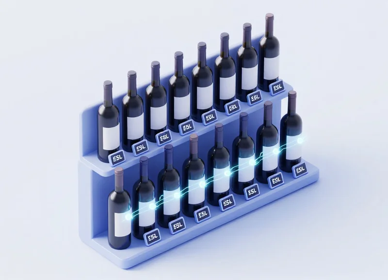
Optimizing the Cleaning Cycle with Real-time Data Analytics

Optimizing the cleaning cycle with real-time data analytics involves using high-temperature RFID tags to automatically capture and log every sterilization event, chemical exposure, and thermal peak a wafer box undergoes. By feeding this telemetry into a Manufacturing Execution System (MES) or a specialized Asset Management Platform, semiconductor facilities can transition from calendar-based maintenance to precision-based cleaning protocols. This data-driven approach ensures that wafer boxes are serviced exactly when needed, preventing the catastrophic yield losses associated with degraded FOUP seals or chemical leaching from over-processed polymers.
- Automated Cycle Counting: Each time a wafer box passes through a cleaning station, the RFID reader logs the event. This eliminates manual logs and provides a 100% accurate count of the box's lifecycle, essential for adhering to strict SEMI safety standards.
- Thermal Stress Profiling: Advanced systems don't just count cycles; they record the duration and peak temperature of each sterilization. Analytics engines use this to calculate the 'Thermal Age' of the box, which is often more accurate than simple cycle counts.
- Predictive Contamination Flagging: When a box reaches 90% of its validated lifespan, the system automatically redirects it to a deep-clean or decommissioning queue, preventing the use of fatigued materials in high-stakes production runs.
| Metric | Legacy Manual Tracking | RFID-Enabled Analytics |
|---|---|---|
| Data Accuracy | Low (Subject to human error) | High (Automated timestamps) |
| Maintenance Logic | Reactive or Time-based | Proactive and Usage-based |
| Contamination Risk | Moderate (Missed cycles) | Minimal (Hard-stop triggers) |
| Asset Utilization | Inefficient (Under/Over-cleaning) | Optimized (Data-backed rotations) |
Expert Insight: The 'Leaching Index' Strategy. A unique advantage of granular RFID data is the ability to track 'Chemical Memory.' Over time, even high-performance polymers like PEEK can absorb trace amounts of process chemicals during cleaning. By correlating RFID-tracked wash history with wafer yield data, engineers can develop a 'Leaching Index.' This allows the fab to retire boxes before they start outgassing contaminants onto fresh silicon—a proactive move that legacy tracking systems simply cannot support.
Can RFID data help identify failing cleaning equipment?
Yes. If the RFID data shows that a specific batch of wafer boxes passing through 'Cleaner A' has a higher defect rate than those from 'Cleaner B,' the system can flag the equipment for immediate calibration.
What happens if a tag fails mid-cycle?
Modern analytic platforms use 'Last Known State' logic. If a box is checked into a cleaner but not checked out, the system flags it for manual inspection to ensure the box wasn't damaged by an equipment malfunction.
Does this integration require a complete MES overhaul?
No. Most RFID middleware can bridge the gap by sending XML or JSON packets to existing MES via standard APIs, allowing for incremental upgrades.
Testing and Validation: Thermal Stress and Chemical Resistance

Validating high-temperature RFID tags for semiconductor environments requires a multi-stage protocol known as Accelerated Life Testing (ALT). This process simulates the cumulative stress of 500 to 1,000 cleaning and sterilization cycles by subjecting tags to extreme thermal gradients (ranging from -40°C to +250°C) and aggressive chemical exposure. The objective is to verify that the bond between the RFID chip and the antenna remains intact and that the protective encapsulation prevents moisture or ionic contaminants from causing electrical shorts or detuning the tag's resonance frequency.
| Test Category | Target Parameter | Benchmark Standard |
|---|---|---|
| Dry Heat Soak | 200°C+ for 1,000 hours | Zero bit-error rate (BER) |
| Thermal Shock | -40°C to 180°C (30 sec transition) | IPC-TM-650 Method 2.4.7 |
| Chemical Resistance | pH 1 to pH 13 immersion | ISO 16750-5 (Chemical Load) |
| Autoclave Testing | 121°C at 15 psi (Moisture) | JEDEC JESD22-A102 |
- Phase 1: Baseline Sensitivity Profiling: Before exposure, record the minimum turn-on power (Pmin) and backscatter strength across the entire UHF or HF band. This establishes a 'digital twin' of the tag's performance.
- Phase 2: Cyclic Thermal Stress: Subject tags to rapid heating and cooling cycles. This identifies coefficient of thermal expansion (CTE) mismatches between the tag substrate and the wafer box material.
- Phase 3: Corrosive Agent Immersion: Expose tags to common Fab cleaning agents, including SPM (Sulfuric-Peroxide Mixture) and dilute HF, to ensure the polymer housing does not crack or become porous.
- Phase 4: Post-Stress Read-Range Analysis: Re-measure sensitivity. A degradation of >3dB in sensitivity typically indicates impending failure of the chip-to-antenna interconnect.
Expert Insight: Beware of the 'Thermal Hysteresis' effect. In our experience, many high-temp tags pass initial heat tests but fail during the cooling phase of the sterilization cycle. This happens because micro-fractures in the adhesive or solder expand during heat and then contract, potentially severing the electrical connection as the tag returns to room temperature. Always perform 'hot-read' and 'cold-read' tests to ensure the tag remains functional at both ends of the temperature curve.
How many sterilization cycles should we simulate?
For wafer boxes, we recommend simulating at least 1.5x the expected lifecycle of the box, typically around 500 to 750 cycles, to account for safety margins.
What is the most common failure point during testing?
Delamination is the primary culprit. When the encapsulation material peels away from the tag substrate, chemicals seep in and corrode the aluminum or copper antenna.
Can standard RFID readers detect degraded tags?
Standard readers may still 'see' a tag, but they won't show the reduced sensitivity. Specialized RFID diagnostic tools are required to measure the analog margin before a complete failure occurs.
Cost-Benefit Analysis: The ROI of Automated Wafer Box Tracking
The Return on Investment (ROI) for automated wafer box tracking is defined by the delta between the high upfront cost of chemically-resistant, high-temperature RFID tags and the long-term elimination of manual scanning labor, reduced asset shrinkage, and the mitigation of catastrophic yield loss. In a typical 300mm fab, the transition from manual barcode entry to automated RFID tracking results in a 15-25% improvement in FOUP (Front Opening Unified Pod) utilization rates and typically achieves break-even within 12 to 18 months of deployment.
| Metric | Manual Barcode/Paper Tracking | Automated High-Temp RFID |
|---|---|---|
| Data Collection Labor | High (Requires line-of-sight & manual scan) | Near-Zero (Hands-free bulk reading) |
| Tracking Error Rate | 1% - 3% (Human error/smudged labels) | < 0.01% (Encrypted digital ID) |
| Cycle Count Accuracy | Estimated (Based on manual logs) | Exact (Real-time wash cycle logs) |
| Asset Search Time | 5-10 mins per shift/operator | Real-time location data |
Expert Insight: The 'Yield Insurance' Value. Beyond labor savings, the most significant ROI driver is the prevention of 'Ghost Lots.' When a wafer box skips a sterilization cycle due to manual logging errors, it can contaminate an entire lot of 25 wafers. At $20,000+ per wafer, a single prevented contamination event can pay for the entire fab's RFID infrastructure five times over. We view high-durability RFID tags not as a tracking expense, but as a yield insurance policy.
- Phase 1: Direct Labor Cost Reduction: Calculate the total hours spent by technicians scanning boxes at the entry and exit of cleaning stations. Multiply by the hourly fully-burdened rate to find the baseline waste.
- Phase 2: Asset Optimization: Use RFID data to identify 'zombie boxes' that are stuck in the cleaning loop or sitting idle. Reducing the total FOUP inventory by even 5% through better utilization saves millions in CAPEX.
- Phase 3: Scrap and Rework Mitigation: Quantify the historical cost of wafer lots lost to cross-contamination or incorrect process routing—all of which are virtually eliminated by automated validation.
What is the typical lifespan of a high-temp RFID tag?
Premium tags are rated for 500 to 1,000 sterilization cycles involving high-pressure steam and harsh chemicals, lasting approximately 2-4 years in a high-volume fab environment.
How does RFID reduce WIP (Work In Progress) inventory?
By providing real-time visibility into the cleaning queue, fabs can reduce the 'buffer' stock of clean boxes required to keep the line moving, effectively lowering the Total Cost of Ownership (TCO).
Is the cost of the readers significant?
While readers represent a fixed cost, the use of passive tags ensures the per-unit cost remains low, making the system highly scalable as the fab expands.
Future-Proofing Your Semiconductor Logistics with DragonGuardGroup
Future-proofing semiconductor logistics requires moving beyond generic industrial RFID tags to specialized components that treat thermal and chemical resistance as a baseline, not a feature. As fab facilities transition to more aggressive sterilization protocols and shorter cycle times, the 'fail-safe' nature of DragonGuardGroup tags ensures that data integrity is maintained through hundreds of 200°C+ exposure events. By integrating DragonGuardGroup’s high-frequency (HF) and ultra-high-frequency (UHF) solutions, manufacturers achieve a seamless digital twin of their wafer carriers, enabling real-time location systems (RTLS) that do not degrade under the corrosive influence of sulfuric acid or hydrogen peroxide washes.
| Feature | Standard Industrial Tag | DragonGuard High-Temp Series |
|---|---|---|
| Peak Temp Tolerance | 85°C - 120°C | 235°C (Short term) / 180°C (Continuous) |
| Chemical Resistance | Splash-proof only | Full immersion (IP68/IP69K) - Acids/Bases |
| Memory Retention | Loss possible after 50 cycles | 10+ years at high-temp exposure |
| Housing Material | Basic ABS/PC | Proprietary PPS/Ceramic Encapsulation |
Expert Insight: Most failures in wafer box tracking occur not due to chip failure, but due to 'coefficient of thermal expansion' (CTE) mismatch. DragonGuardGroup utilizes a proprietary vacuum-epoxy potting technique that matches the expansion rate of the internal antenna with the outer PPS shell. This eliminates micro-cracks that typically allow cleaning fluids to seep in and corrode the IC over time.
- Custom Antenna Tuning: DragonGuardGroup provides specific antenna offsets to account for the proximity of metallic wafer shields, ensuring 99.9% read rates even in dense storage environments.
- Scalable Data Mapping: Tags are available with user-defined memory sectors, allowing for the storage of maintenance logs and cycle counts directly on the wafer box, reducing latency in offline zones.
- Sustainability & Lifecycle Management: With an operational life exceeding 1,000 wash cycles, these tags reduce the electronic waste associated with frequent tag replacements in high-volume fabs.
Can DragonGuardGroup tags be retrofitted to existing wafer FOUPs?
Yes, we offer both bolt-on and adhesive-mount versions designed to fit standard SEMI-compliant carrier footprints without interfering with automated material handling systems (AMHS).
What is the typical read range for these high-temp tags?
Depending on the reader power and environment, our UHF tags achieve a stable read range of 2-5 meters, while HF/NFC variants are optimized for close-range 1-10cm precision tracking.
Are the materials used in the tags cleanroom certified?
Absolutely. All DragonGuard semiconductor tags are manufactured with outgassing-compliant materials to ensure they do not introduce contaminants into Class 1 cleanroom environments.