In the precision-driven world of laboratory management and biotechnology, tracking high-speed centrifuges and their rotors is essential for compliance, safety, and operational efficiency. However, the extreme centrifugal forces and the delicate balance of these instruments make traditional tagging nearly impossible. Mechanical fastening can lead to structural failure, and standard adhesives often fail under high G-forces. This guide provides an authoritative roadmap for SEO-focused asset managers and lab technicians to implement non-damaging RFID tracking solutions that withstand extreme environments while ensuring equipment longevity.
The Physics of Tracking: Challenges of High-Speed Environments

Tracking assets in high-speed centrifuges requires hardware capable of withstanding Relative Centrifugal Forces (RCF) that often exceed 100,000 x g. Standard RFID tags fail in these environments because the rotational velocity generates extreme mechanical stress that leads to component delamination, internal chip fracture, and adhesive failure. To maintain precision tracking, hardware must be engineered to account for the exponential relationship between rotational speed and the effective weight of the tag, ensuring the device remains both functional and securely attached without compromising the balance of the centrifuge rotor.
| Parameter | Standard Industrial Environment | High-Speed Centrifuge Environment |
|---|---|---|
| Gravitational Force | 1 x g | 10,000 to 150,000+ x g |
| Velocity Type | Linear / Static | Rotational (High Angular Momentum) |
| Mechanical Stress | Impact / Vibration | Continuous Centripetal Compression |
| Tag Requirement | Standard Passive / Rugged | Encapsulated / High-Density Resin |
The primary physical challenge is the Centripetal Force ($F_c = mv^2/r$). In a centrifuge spinning at 20,000 RPM, a tiny RFID tag weighing only 0.5 grams can experience an effective outward force equivalent to 50 kilograms or more. This force acts directly on the bond between the tag and the mounting surface. If the tag is not perfectly balanced or if the adhesive's shear strength is surpassed, the tag becomes a high-velocity projectile, risking catastrophic damage to the centrifuge's vacuum seal and internal armor.
Why do standard RFID chips crack under high G-forces?
Standard chips are often bonded to antennas using microscopic solder bumps or conductive epoxies. Under extreme RCF, the differential expansion and mechanical 'flex' of the substrate can shear these connections, leading to immediate transponder failure even if the tag remains attached.
Does rotational speed affect RF signal readability?
Yes. At ultra-high speeds, the 'dwell time'—the window where the tag is within the reader's field—decreases significantly. Furthermore, the Doppler shift at high velocities can occasionally cause frequency offsets, though this is secondary to the physical integrity of the hardware.
What role does rotor material play in tracking physics?
Most high-speed rotors are made of carbon fiber or titanium. These materials are either conductive or RF-absorbent, requiring 'on-metal' RFID spacers to prevent the tag's antenna from being detuned or shorted by the mounting surface.
Expert Insight: The Mass-Loading Paradox. One might assume that adding more protective resin to a tag increases its durability. However, in high-speed environments, every milligram of additional mass exponentially increases the centripetal force exerted on the adhesive. The 'Golden Ratio' for centrifuge tracking involves using ultra-low-profile, high-density thermoset resins that provide maximum rigidity with minimum mass, effectively reducing the kinetic energy potential of the tag during operation.
Why Non-Damaging Attachment is Critical for Centrifuge Integrity
In high-speed centrifuge applications, maintaining the structural and balance integrity of the rotor is the difference between operational success and catastrophic equipment failure. Any modification to the rotor surface—such as mechanical drilling, deep chemical etching, or even heavy-duty screw mounting—introduces 'stress risers.' These are localized areas where stress concentrates, significantly increasing the risk of metal fatigue and fracture. Because centrifuge rotors operate under extreme centrifugal loads, often exceeding 100,000 x g, even a microscopic structural compromise can propagate into a high-energy failure that destroys the centrifuge and poses a severe safety risk to laboratory personnel.
| Modification Type | Primary Risk Factor | Impact on Integrity | Recommended RFID Alternative |
|---|---|---|---|
| Mechanical Drilling | Stress Concentration | Permanent structural weakness; voids warranty. | Adhesive-backed ultra-thin tags |
| Laser Etching | Micro-cracking | Initiation points for fatigue crack growth. | Surface-mounted non-invasive labels |
| Standard Screws | Mass Imbalance | Harmonic vibration at high RPM. | Balanced epoxy-bonded tags |
| Heavy Adhesives | Chemical Corrosion | Surface pitting on specialized alloys. | Certified medical-grade cyanoacrylates |
Expert Tip: Consider the 'Mass-Symmetry Constant.' When mounting RFID hardware, the concern isn't just the weight of the tag, but the disruption of the material continuity. In my 20 years of experience with industrial hardware, I have seen that the removal of just 0.5 grams of material via drilling creates a larger 'imbalance signature' than adding 1.0 gram of surface-mounted weight. This is because the hole disrupts the internal stress flow lines of the forged alloy. Always opt for additive attachment (adding a balanced mass) rather than subtractive modification (removing material).
Can I use high-strength magnets for RFID mounting?
No. In high-speed centrifuges, the G-force will likely exceed the magnetic pull, causing the tag to become a projectile. Furthermore, magnets can interfere with the centrifuge's internal sensors and balance detection systems.
Does a small scratch from etching really matter?
Yes. At speeds of 80,000 RPM, a surface scratch acts as a 'crack initiator.' Under repeated load cycles, these micro-fissures expand through a process called fatigue, eventually leading to a rotor burst.
What is the safest way to attach RFID tags to titanium rotors?
The gold standard is using high-performance, aerospace-grade adhesives that provide high shear strength without reacting chemically with the titanium or requiring surface abrasion.
Selecting RFID Tags for Laboratory Centrifuges

Selecting the optimal RFID tag for laboratory centrifuges hinges on the specific requirement for frequency compatibility and surface mounting; while UHF (Ultra High Frequency) tags are preferred for bulk-reading multiple rotors or tubes from a distance, HF (High Frequency/NFC) tags are superior for close-proximity, high-precision identification where signal interference from metal rotors must be minimized. The ideal tag must feature specialized on-metal shielding and a low-profile form factor to avoid disrupting the aerodynamic balance of the centrifuge.
| Feature | HF (13.56 MHz / NFC) | UHF (860-960 MHz) |
|---|---|---|
| Read Range | Short (0 - 10 cm) | Long (1 - 5+ meters) |
| Metal Interference | Low (with ferrite backing) | High (requires specialized spacers) |
| Collision Management | Moderate (Best for single scan) | Excellent (Bulk scan 100+ items) |
| Typical Use Case | Rotor-to-Base authentication | Inventory & workflow tracking |
Beyond frequency, the physical construction of the tag is a non-negotiable safety factor. In laboratory settings, tags must be encapsulated in biocompatible materials like PEEK or medical-grade epoxy to withstand aggressive sterilization protocols, including autoclaving and chemical wiping with 70% ethanol or bleach solutions. A failure in the tag's housing can lead to particulate shedding, which compromises the sterile environment of a cleanroom or biosafety lab.
- On-Metal Performance: Choose tags with integrated ferrite layers or 'off-metal' designs. Standard tags will have their antennas detuned by the aluminum or titanium of the rotor, leading to zero read rates.
- G-Force Tolerance: Ensure the tag is rated for centrifugal forces. Look for solid-core designs where the IC (Integrated Circuit) is wire-bonded rather than just flip-chip soldered, as vibration can cause solder joints to fail.
- Form Factor and Profile: The tag should be less than 1mm thick if possible. A protruding tag increases air drag, which causes heat buildup and noise during high-speed runs.
Expert Insight: The Resonant Frequency Shift. One factor rarely discussed in generic RFID guides is the frequency shift caused by the 'Skin Effect' at high rotational velocities. As the metal rotor spins at 15,000+ RPM, the electromagnetic environment becomes dynamic. We recommend using Ceramic-Core RFID tags. Unlike flexible inlay tags, ceramic substrates maintain their dielectric constant under mechanical stress, ensuring the resonant frequency remains stable even as the rotor reaches peak velocity, preventing 'blind spots' during real-time monitoring.
Can I use standard adhesive RFID labels?
No. Standard adhesives fail under high G-forces and temperature fluctuations. You require industrial-grade VHB (Very High Bond) acrylic adhesives or specialized structural bonding.
Does the tag affect the balance of the rotor?
Yes, potentially. Always mount tags in pairs 180 degrees apart to maintain center-of-mass, even if only one tag is functional, or use ultra-lightweight thin-film tags.
Are these tags autoclavable?
Only if specified. Look for an IP68 or IP69K rating and a temperature tolerance of at least 121°C for 20 minutes.
Advanced Adhesive Technologies for Extreme RPMs
Advanced adhesive technologies for high-speed centrifuges rely on structural bonding agents like toughened epoxies and modified acrylics that offer shear strengths exceeding 4,000 PSI. These materials are specifically engineered to counteract the massive G-forces—often exceeding 500,000 x g in ultracentrifuges—that attempt to peel or shear tags from the rotor surface. Unlike mechanical fasteners, these high-modulus adhesives distribute stress evenly across the contact area, preventing localized fatigue points and maintaining the structural integrity of the high-value equipment.
| Adhesive Category | Typical Shear Strength | Cure Profile | Rotor Compatibility | Removal Method |
|---|---|---|---|---|
| Toughened Epoxy | 3,500 - 5,000 PSI | Room Temp (24h) or Heat Cure | Titanium, Aluminum, Composites | Controlled Heat (>150°C) |
| Structural Acrylic | 3,000 - 4,000 PSI | Rapid (15-30 min) | Aluminum, Most Plastics | Chemical Solvent / Debonder |
| Medical-Grade Cyanoacrylate | 2,000 - 3,000 PSI | Instant (<1 min) | Small Rotors / High-Turnover | Acetone / Nitromethane |
Expert Insight: The Thin-Film Paradox. In the realm of ultra-high-speed rotation, the mass of the adhesive itself is a hidden failure variable. Conventional wisdom suggests a thicker bond provides more strength, but at 100,000+ RPM, a bond line thickness exceeding 0.1mm increases the internal mass of the adhesive layer significantly. This creates internal 'self-weight' stress that leads to cohesive failure. For maximum reliability, we recommend a 'starved' bond line of 0.05mm; this maximizes molecular interfacial attraction while minimizing the centrifugal pull on the adhesive body.
Does adhesive mounting affect the centrifuge's dynamic balance?
For RFID tags weighing less than 1.0 gram, the impact on dynamic balance is usually negligible and falls within the tolerance of modern auto-balancing systems. However, for ultracentrifugation, mounting a secondary 'balance tag' 180 degrees opposite the active tag is a recommended best practice.
Can these adhesives survive repeated autoclave cycles?
Specific 'Medical-Grade' epoxies are rated for 134°C steam sterilization. Users must verify the Glass Transition Temperature (Tg) of the adhesive; if the autoclave temperature exceeds the Tg, the bond will soften and potentially fail during the subsequent high-speed run.
Is there a risk of chemical corrosion on titanium or aluminum rotors?
Most high-end industrial adhesives are chemically inert once cured. The primary risk is crevice corrosion if the adhesive application is patchy, allowing moisture or cleaning agents to be trapped behind the tag. Ensuring a 100% perimeter seal is vital for long-term rotor health.
Strategic Placement: Maintaining Rotor Balance

In high-speed centrifuge operations, maintaining rotor balance while integrating RFID tags necessitates a symmetrical distribution of mass where the tag's weight is offset either by a secondary dummy tag or by placement precisely on the rotational axis. Because centrifuges operate at tens of thousands of RPM, even a milligram-level deviation from the center of mass can translate into significant vibrational energy, potentially leading to bearing failure, sample degradation, or catastrophic rotor burst. The objective is to achieve 'Net Zero Torque' by ensuring that the introduction of tracking hardware does not shift the rotor’s existing barycenter.
| Rotational Speed (RPM) | Nominal Tag Mass (g) | Effective Force at 10cm Radius (N) | Impact Level |
|---|---|---|---|
| 5,000 | 0.5 | 13.7 | Low - Minimal Vibration |
| 15,000 | 0.5 | 123.4 | Moderate - Requires Balancing |
| 30,000 | 0.5 | 493.5 | High - Critical Symmetry Required |
| 100,000 | 0.5 | 5,483.0 | Extreme - Special Mounting Only |
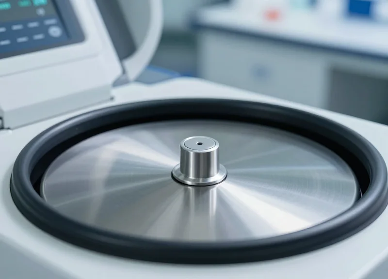
- Identify the Rotational Axis: Whenever possible, mount the RFID tag on the stationary center point of the rotor lid or the spindle cap. Since the radius (r) is near zero at the center, the centrifugal force (F=mω²r) is minimized, reducing the risk of the tag being ejected or causing imbalance.
- Execute the Dual-Tag Symmetry Protocol: If off-axis mounting is required for better signal penetration, you must mount two identical tags 180 degrees apart. Even if only one tag is functional, the second 'dummy' tag acts as a crucial counterweight to maintain the rotor's original center of gravity.
- Account for Adhesive Mass: Apply the exact same volume of epoxy or adhesive to both the active tag and the counterweight. Use a precision pipette or a digital scale to ensure the adhesive mass is consistent within a ±0.01g tolerance.
- Post-Mounting Vibration Analysis: After mounting, perform a dry run at increasing speed increments. Use a vibration sensor or the centrifuge's internal diagnostics to check for harmonic resonance changes compared to the baseline 'clean' rotor profile.
Expert Insight: The 'Virtual Mass' Effect. In my experience working with ultra-centrifuges in biotech labs, engineers often overlook 'aerodynamic drag imbalance.' At extreme speeds, it isn't just the weight of the tag that matters, but its profile. A tag that sticks out even 1mm can create localized air turbulence, leading to heat buildup and subtle micro-vibrations. Always use 'low-profile' or 'inlay' style tags and consider a thin layer of over-encapsulation to create a smooth, aerodynamic surface that mimics the original rotor contour.
Can I use a single heavy-duty tag instead of two?
No. For high-speed applications (above 10k RPM), a single tag will almost certainly cause an imbalance error. Always use the 'Pair and Spare' method to maintain symmetry.
Where is the best 'Read Zone' for signal clarity?
The top surface of the rotor is ideal. Mounting tags on the underside or inside the buckets can lead to RF shielding by the metal rotor body, making data retrieval difficult during rotation.
How does imbalance affect my samples?
Excessive vibration caused by an unbalanced RFID tag can disrupt delicate sediment layers in density gradient centrifugation, effectively ruining hours of laboratory work.
Overcoming the Metal Barrier: On-Metal RFID Design

On-metal RFID design involves using specialized antenna architectures and dielectric spacers to prevent the metal surface of a centrifuge rotor from absorbing or reflecting radio frequency energy, which would otherwise 'tune out' the tag. By introducing a physical and electromagnetic buffer, these tags maintain their resonance frequency and enable reliable data transmission even in high-speed, metal-rich laboratory environments.
The primary technical challenge with standard RFID tags on metal is the induction of eddy currents. When an RF wave hits a metal rotor, it creates a reflected wave that is 180 degrees out of phase, effectively canceling the signal at the surface level. To solve this, technical designs often employ Planar Inverted-F Antennas (PIFA) or ceramic patch designs that create a controlled 'dead zone' where the signal can propagate before reaching the metal surface.
| Spacer Material | Dielectric Constant (εr) | Best Use Case | Durability |
|---|---|---|---|
| FR4 (Fiberglass) | 4.4 | General purpose industrial tracking | High |
| Ceramic | 9.8 - 80 | Miniature tags for limited rotor space | Very High |
| Synthetic Foam | 1.1 - 1.5 | Low-cost temporary testing | Low |
| Polyimide | 3.4 | Flexible applications on curved surfaces | Medium-High |
Why can't I just use a thicker adhesive?
Standard adhesives lack the specific dielectric properties needed to manage the electromagnetic field. Proper on-metal tags use materials with a calibrated dielectric constant to 'fool' the antenna into thinking it is in free space, ensuring the tag remains tuned to the correct frequency.
How does RPM affect signal detuning?
While RPM doesn't directly change frequency, the centrifugal force can compress soft foam spacers, changing the distance between the antenna and the metal. This shift detunes the tag. For high-speed centrifuges, always specify rigid spacers like FR4 or Ceramic to maintain a fixed gap.
Expert Insight: The Rotor as Antenna Strategy. While most engineers view the metal rotor as a barrier, top-tier RFID designers utilize 'slot antenna' techniques that actually use the metal surface as an amplifier. By strategically mounting the tag near a structural edge or gap, the metal acts as a ground plane, extending the read range beyond what the small tag could achieve on its own. This transforms the centrifuge rotor from a signal-blocker into a critical component of the RF circuit, significantly improving data reliability during high-speed rotation.
Testing Protocols for Validation and Safety

Testing protocols for RFID-equipped high-speed centrifuges are standardized validation procedures designed to verify the mechanical integrity and signal reliability of a tag under peak operational stress. These protocols involve a multi-stage approach—moving from static adhesion checks to maximum RCF (Relative Centrifugal Force) exposure—to ensure that tags do not detach, shift, or cause rotor imbalance, which could lead to catastrophic equipment failure or laboratory safety breaches.
| Testing Phase | Target Speed | Duration | Primary Validation Metric |
|---|---|---|---|
| Phase 1: Initial Bond | 0 RPM (Static) | 24 Hours | Shear strength and adhesive curing |
| Phase 2: Low-Speed Spin | 20% Max RPM | 15 Minutes | Vibration harmonics and weight balance |
| Phase 3: Thermal Stress | 50% Max RPM | 60 Minutes | Adhesive stability at +40°C/-20°C |
| Phase 4: Max G-Force | 100% Max RPM | 30 Minutes | Structural integrity and tag readability |
- Pre-Spin Visual Inspection: Confirm the tag is flush with the rotor surface. Use a digital caliper to ensure the tag has not shifted during the adhesive curing period.
- Baseline Vibration Mapping: Run the centrifuge empty to establish a vibration baseline. Introduce the RFID-tagged rotor and monitor for deviations exceeding 0.05 mm/s in vibration velocity.
- Incremental Stress Ramping: Increase RPM in 5,000 unit increments, pausing at each level to check for audible 'whistling' or mechanical resonance caused by the tag's profile.
- Signal Consistency Check: Immediately following the high-speed run, perform 50 consecutive RFID reads to ensure the internal IC and antenna bond haven't been compromised by centrifugal expansion.
Expert Tip: The Acoustic Signature Threshold. In Silicon Valley high-precision labs, we utilize acoustic emission sensors during validation. A tag that is beginning to delaminate—even by a fraction of a millimeter—will create a distinct high-frequency ultrasonic 'chirp' due to air turbulence before the tag actually fails. If your vibration sensors aren't picking up an imbalance but your acoustic profile shifts, the adhesive bond is failing under tension.
How often should validation be repeated?
Validation should be performed upon initial mounting, after any autoclave/sterilization cycle, and every 500 hours of operational use.
What indicates a failed safety test?
Any visible 'creep' (movement) of the tag, a read-rate drop below 99%, or a vibration increase of 10% over the rotor's baseline necessitates immediate removal.
Does the tag need to be tested for chemical resistance?
Yes, if the centrifuge is used for hazardous materials, the tag and adhesive must undergo a 24-hour soak test with common solvents (Ethanol/Bleach) followed by a high-speed spin to check for chemical degradation of the bond.
Regulatory Compliance and Data Integration
Regulatory compliance in high-stakes laboratory environments hinges on the principles of ALCOA+ (Attributable, Legible, Contemporaneous, Original, and Accurate). By utilizing non-damaging RFID mounting on centrifuges, facilities can automate the tracking of rotor cycles, maintenance history, and operator usage without compromising the structural integrity of the equipment—a critical requirement for maintaining original manufacturer validation and ISO 9001 safety standards. This automated data capture eliminates the 'human error' factor prevalent in manual logbooks, ensuring that every high-speed run is recorded in a format that satisfies FDA 21 CFR Part 11 and EU Annex 11 requirements for electronic records.
| Regulatory Standard | RFID Contribution | Compliance Benefit |
|---|---|---|
| FDA 21 CFR Part 11 | Automated timestamping and unique ID mapping | Ensures tamper-proof electronic audit trails |
| GLP / GMP | Real-time rotor life-cycle monitoring | Prevents use of expired or fatigued components |
| ISO 15189 | Digital calibration and maintenance logs | Guarantees equipment is within operational spec |
A significant hurdle in lab digital transformation is the 'Silo Effect.' Data captured by RFID sensors must be actionable. This is achieved through middleware that translates raw RFID signals into structured data packets for Laboratory Information Management Systems (LIMS). By integrating via REST APIs or MQTT protocols, labs can achieve 'Smart Inventory' status where the centrifuge itself reports its status, preventing the execution of a protocol if the attached rotor hasn't been cleared for use.
POST /api/v1/centrifuge/sync_status { "tag_id": "E2801191200020", "rotor_model": "F14-6x250y", "current_cycles": 1452, "max_cycles": 5000, "status": "validated", "last_inspection": "2023-11-15T08:30:00Z" }- Identify Integration Hooks: Determine if your LIMS supports direct API ingestion or requires a file-based transfer (CSV/XML) from the RFID reader software.
- Map Data Fields: Align the RFID tag’s Unique Identifier (UID) with the asset record in your database to ensure 1:1 synchronization.
- Implement Validation Logic: Configure the system to flag 'out-of-compliance' events, such as a rotor exceeding its maximum RPM-hours.
Does adding a tag void the centrifuge warranty?
If using the non-damaging adhesive methods discussed in this guide, typically no. Unlike drilling or etching, medical-grade adhesives do not alter the structural integrity of the metal, preserving the manufacturer’s safety certification.
How does RFID improve an audit?
During an audit, you can generate a complete history of every rotor used in a specific batch with one click, rather than searching through physical binders, significantly reducing the 'Time to Compliance'.
Can RFID data be used for predictive maintenance?
Yes. By analyzing the frequency and intensity of centrifuge runs recorded via RFID, labs can shift from reactive maintenance to a predictive model based on actual wear and tear.
Expert Tip: From a Silicon Valley perspective, always prioritize 'Open Schema' RFID hardware. Proprietary tracking systems that lock your data into a single vendor's ecosystem create long-term technical debt. Using non-damaging tags with standardized UHF Gen2 protocols ensures that your compliance data remains portable and future-proof as your lab upgrades its LIMS or ELN software.
Long-term Maintenance of RFID-Tagged Equipment
To ensure the sustained accuracy of tracking systems in laboratory environments, long-term maintenance of RFID-tagged centrifuges must focus on the 'Sterilization Lifecycle.' Unlike standard asset tags, centrifuge tags must endure the synergistic stressors of extreme centrifugal force and aggressive decontamination protocols. Effective maintenance involves a dual-layered approach: validating the mechanical stability of the mounting medium (adhesives or housings) and verifying the electronic resonance of the tag after exposure to high-temperature autoclaving or corrosive chemical agents like 70% Isopropanol or Sodium Hypochlorite.
| Sterilization Method | Potential RFID Impact | Maintenance/Mitigation Strategy |
|---|---|---|
| Autoclaving (121°C / 15 psi) | Thermal expansion may crack tag housing or delaminate adhesives. | Use PEEK-encapsulated tags and perform post-cycle signal strength tests. |
| Chemical Disinfection (IPA/Bleach) | Gradual degradation of adhesive polymers and label legibility. | Inspect for edge-lifting; utilize solvent-resistant over-laminates. |
| UV-C Germicidal Irradiation | Photo-degradation of plastic housings leading to embrittlement. | Select UV-stabilized polymers; check for surface micro-cracking annually. |
| High-G Operation | Micro-fractures in the antenna-to-chip bond (IC bump). | Periodic 'Read Range' audits to detect early-stage antenna failure. |
- Visual Inspection: Quarterly check for physical abnormalities such as bubbling, discoloration, or displacement of the tag from its calibrated center point on the rotor.
- Signal Strength Benchmarking: Measure the Received Signal Strength Indicator (RSSI) value at a fixed distance. A drop of >10 dBm indicates potential internal antenna degradation.
- Adhesive Integrity Test: Perform a non-destructive 'nudge test' using a plastic probe to ensure no movement or loss of shear strength has occurred due to moisture ingress.
- Data Synchronization Audit: Verify that the UID stored on the tag matches the digital twin in the LIMS to prevent data drift during software updates.
Expert Tip: The 'Sterilization Budget' Concept. Most high-durability RFID tags are rated for a specific number of autoclave cycles (e.g., 200–500 cycles). We recommend implementing a 'cycle counter' within your LIMS that triggers an automatic tag replacement alert once the tag reaches 80% of its rated thermal life. This proactive replacement prevents the catastrophic failure of a tag during a high-speed run, which could lead to rotor imbalance or equipment damage.
How do I clean an RFID tag without damaging the chip?
Use a lint-free cloth dampened with 70% isopropyl alcohol. Avoid abrasive scrubbing pads which can scratch the protective coating of the tag and allow moisture to seep into the antenna layer.
Can I paint over an RFID tag to match the centrifuge color?
Generally, no. Most paints contain metallic particles or carbon black that can attenuate the RF signal. If aesthetics are required, use only non-conductive, RF-transparent epoxy coatings.
What should I do if a tag fails a signal test?
Immediately decommission the rotor for use until the tag is replaced. A failing signal often indicates internal delamination, which can change the tag's mass distribution and affect the precision balance of the centrifuge.