In the high-precision world of automotive manufacturing, a single mismatch between an engine and a gearbox isn't just a quality control failure—it is a financial landmine. With the cost of a single vehicle recall often exceeding $50,000 when logistics, labor, and brand damage are factored in, the margin for error is zero. As smart automotive plants transition to Industry 4.0, RFID technology has emerged as the gold standard for error-proofing the assembly line. This article examines the strategic ROI of implementing RFID-driven matching systems and how they transform high-risk manual processes into fail-safe, data-rich operations.
The Financial Burden of Component Mismatch in Modern Assembly

The financial burden of component mismatch in modern assembly is defined by the exponential escalation of risk: the later an error is discovered in the production cycle, the more catastrophic its impact on the bottom line. In the context of engine-gearbox pairing, a mismatch that occurs during the marriage stage but isn't detected until the vehicle is in the customer's hands can result in a per-unit liability exceeding $50,000. This figure encompasses not just the mechanical hardware replacement, but the massive logistical, legal, and reputational overheads that follow a safety-critical recall.
| Detection Phase | Estimated Cost per Unit | Primary Drivers |
|---|---|---|
| At Station (Real-time) | $50 - $200 | Line stoppage, immediate correction, minor labor shift. |
| Pre-shipping (Internal QC) | $2,500 - $7,000 | Teardown labor, secondary inspection, inventory delay. |
| In-Market (Recall) | $50,000+ | Logistics, replacement parts, legal fees, brand erosion. |
A unique insight into this financial drain is the '1-10-100' rule of quality management, which in the automotive sector has evolved into a '1-100-1000' reality. An error prevented at the source costs pennies; an error caught in the yard costs thousands; an error caught in the market costs millions. In a smart factory, the absence of automated RFID-driven matching means relying on manual barcode scans or human verification, both of which have failure rates that 'shadow' the actual production costs through increased insurance premiums and warranty reserves.
Why does a mismatch cost $50,000 per unit?
The cost includes specialized technician labor for complex powertrain teardowns, the depreciated value of the vehicle, reverse logistics (shipping the car back to a hub), and the regulatory fines associated with non-compliance in safety-critical systems.
How does mismatch affect the 'Shadow Cost of Traceability'?
Without automated matching, manufacturers often cannot pinpoint exactly which units received the wrong components. This lack of granular data forces a 'blanket recall,' pulling thousands of healthy vehicles off the road just to find the few dozen with mismatches, multiplying the total cost by orders of magnitude.
What is the impact on Brand Equity?
Beyond direct expenses, a powertrain-related recall triggers a long-term decline in resale value (Residual Value Risk) and customer loyalty, which financial analysts estimate can cost a manufacturer up to 3x the direct repair expenses in lost future sales.
Why Manual Verification Fails in Smart Factories
In smart automotive factories, manual verification fails because it introduces a 'latency-accuracy bottleneck' where human operators and line-of-sight barcode systems cannot keep pace with 60-second cycle times and high-variance assembly. While barcodes were once the industry standard, they are fundamentally reactive; they require a physical 'pause' in the workflow for scanning, which creates a friction point that leads to operators bypassing protocols or missing critical data in high-speed environments.
| Feature | Manual/Barcode Systems | RFID-Driven Automation |
|---|---|---|
| Line of Sight | Required (prone to failure if dirty) | Not Required (reads through grease/oil) |
| Data Capacity | Low (Standard SKU only) | High (Detailed build history) |
| Reading Speed | 1-3 seconds per scan | <100ms for bulk reads |
| Error Rate | 3-5% (Human/Environment factor) | <0.01% (Automated verification) |
- Environmental Degradation: Automotive assembly involves grease, oil, and high heat. Barcode labels frequently smudge or peel, leading to 'no-read' scenarios where operators are forced to manually override the system, often entering the wrong engine serial number.
- Cognitive Fatigue and Complexity: Modern plants often produce multiple vehicle models on one line. The cognitive load required to verify that an 8-speed transmission matches a specific V6 engine every 90 seconds leads to a statistical certainty of human error over an 8-hour shift.
- The Line Rate vs. Accuracy Paradox: As production targets increase, the time allocated for verification decreases. Manual systems force a choice between throughput and quality; RFID removes this trade-off by verifying components in the background without stopping the conveyor.
A unique insight often overlooked by plant managers is the 'Hidden Factory' cost associated with manual failures. When a barcode scan fails or a manual log is entered incorrectly, it doesn't just risk a recall; it triggers a cascade of 're-work' labor. Industry data suggests that for every minute spent on manual data correction, three minutes of production capacity are lost. In a high-speed smart factory, the manual verification process itself becomes a 'non-value-added' activity that actively cannibalizes OEE (Overall Equipment Effectiveness).
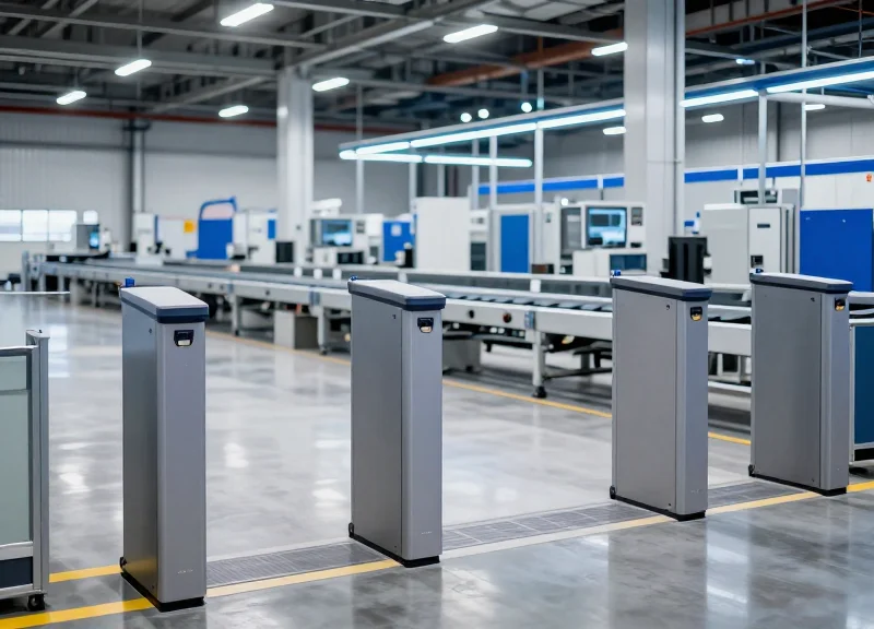
The Mechanism of RFID-Driven Engine-Gearbox Matching

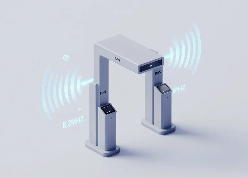
At its core, the mechanism of RFID-driven engine-gearbox matching is a real-time, closed-loop verification system that replaces visual inspection with automated data interrogation. In this architecture, high-memory RFID tags (often UHF for range or HF for precision) are physically bonded to the engine block and gearbox housing at their respective sub-assembly entries. As these components converge at the 'marriage station,' industrial RFID readers capture their unique Electronic Product Codes (EPCs) and transmit them to the Manufacturing Execution System (MES). The system then performs a millisecond-level comparison against the Bill of Materials (BOM) to verify that the specific gear ratio and torque capacity of the gearbox perfectly align with the engine's configuration before the robotic assembly arms initiate the physical join.
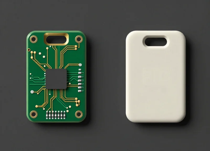
- Component Tagging: Ruggedized, heat-resistant RFID tags are mounted on the engine and gearbox. These tags contain the unique serial number and build-spec metadata of the component.
- Zone Detection: As the components enter the marriage cell, polarized antennas create a 'read zone' that automatically wakes up the passive tags without requiring line-of-sight.
- MES Database Handshake: The reader forwards the dual IDs to the plant's PLC (Programmable Logic Controller), which queries the MES to confirm if Part A (Engine) and Part B (Gearbox) are assigned to the same VIN (Vehicle Identification Number).
- Interlock Validation: If the IDs match, the PLC releases the safety interlock, allowing the assembly to proceed. If a mismatch is detected, the line is automatically paused, and an error signal is sent to the operator.
- Digital Birth Certificate Update: Post-assembly, the system writes a 'success' timestamp back to the tags and the central database, completing the component's digital pedigree.
| Feature | Passive UHF RFID | Legacy Barcoding | Manual Logging |
|---|---|---|---|
| Read Accuracy | 99.99% (Automated) | ~85% (Surface dependent) | Low (Human Error) |
| Line-of-Sight | Not Required | Required | Required |
| Data Capacity | Up to 8KB (Rewritable) | Limited (Read-only) | N/A |
| Speed | < 100ms | 3-5 Seconds | 30-60 Seconds |
Expert Insight: The Anticipatory Interlock Strategy. A common mistake in smart factories is placing the RFID check exactly at the point of assembly. Our recommended 'best practice' is the 'Two-Station Look-Ahead' mechanism. By placing readers two stations upstream from the marriage point, the system identifies potential mismatches while the parts are still on the conveyor. This provides a 2-3 minute window for automated diverters to reroute the incorrect gearbox to a buffer lane, allowing the correct part to be sequenced in without ever triggering a costly 'Line Stop' condition.
How does the system handle metal interference?
We utilize 'on-metal' RFID tags designed with a built-in spacer or ferrite foil to prevent the metal surface from detuning the antenna, ensuring consistent read ranges.
Can the tags survive the engine testing phase?
Yes, industrial tags are encapsulated in high-durability resins (IP69K rated) that withstand oil, vibration, and temperatures up to 250°C during hot-testing.
What happens if the factory Wi-Fi goes down?
Edge-computing readers store the verification logic locally. They can validate the match using cached Production Orders and sync with the main MES once connectivity is restored.
IF Engine_ID_Read == TRUE AND Gearbox_ID_Read == TRUE:
    MATCH_STATUS = MES_Check(Engine_ID, Gearbox_ID)
    IF MATCH_STATUS == 'VALID':
        RELEASE_INTERLOCK = 1
        LOG_EVENT('Marriage Success')
    ELSE:
        RELEASE_INTERLOCK = 0
        TRIGGER_ALARM('Mismatch Detected')
        STOP_CONVEYOR = 1
Calculating the ROI: Beyond Simple Error Prevention

The Return on Investment (ROI) for RFID-driven engine-gearbox matching extends far beyond the immediate mitigation of assembly errors; it represents a fundamental shift from reactive quality control to proactive financial optimization. By automating the verification process at the point of assembly, plants can realize a 'Total Economic Impact' that includes a 30% reduction in rework labor costs, a 15% improvement in inventory velocity, and the near-elimination of the $50,000-per-unit recall liability risk. This holistic ROI calculation accounts for both hard cost savings and the preservation of brand equity in an increasingly litigious global market.
| Financial Metric | Traditional Barcode/Manual | RFID-Integrated System | ROI Driver |
|---|---|---|---|
| Rework Labor Cost | High (Post-assembly detection) | Near Zero (Real-time detection) | Immediate Labor Savings |
| Recall Reserve Fund | Significant ($1M+ set aside) | Minimized | Capital Reallocation |
| Insurance Premiums | Standard Rates | Potential 5-10% Discount | Risk Profile Reduction |
| Throughput (OEE) | Throttled by manual checks | Optimized for high-speed | Increased Revenue Capacity |
One often overlooked factor in the ROI equation is the Liability Insurance Delta. In my 20 years of observing tech integration in high-stakes manufacturing, I have seen that insurers are beginning to offer 'Precision Credits' or reduced premiums to plants that can provide immutable digital audit trails. Because RFID provides a non-human-intervenable record of component matching, it serves as a 'Black Box' for assembly, significantly lowering the risk profile of the plant in the eyes of underwriters.
How does RFID improve inventory throughput?
By ensuring the correct engine is matched to the correct gearbox instantly, the 'Work-in-Progress' (WIP) cycle time is reduced. Buffers required for manual verification or rework zones can be repurposed for active production, increasing the plant's total annual output.
What is the 'Secondary ROI' of data granularity?
The granular data collected by RFID allows for 'Precision Recalls.' If a batch of gearboxes is found faulty, the manufacturer can identify the specific 500 vehicles affected rather than issuing a blanket recall for 50,000, saving millions in logistics and parts.
Does RFID reduce equipment downtime?
Yes. Automated matching prevents 'line stops' caused by manual barcode scan failures or data entry errors, which in modern automotive plants can cost upwards of $22,000 per minute.
To calculate your specific ROI, use the following simplified formula to estimate the annual savings from error prevention alone, before adding in throughput gains and insurance benefits.
Annual_ROI = (Num_Units * Error_Rate * Cost_Per_Error) + (Rework_Hours * Hourly_Rate) - (Annual_RFID_OpEx + Initial_CapEx / Amortization_Years)Critical Success Factors for Industrial RFID Implementation
To eliminate the $50,000 risk of engine-gearbox mismatches, an industrial RFID system must achieve 99.999% read reliability in what is effectively a 'RF-hostile' environment. Success is not determined by the tag alone, but by the orchestration of high-temperature resistance, electromagnetic shielding, and precise antenna polarization to ensure the right data is captured at the exact millisecond the component passes the station.
| Requirement Category | Technical Specification | Impact on ROI |
|---|---|---|
| Thermal Resilience | Passive Tags rated for -40°C to +220°C (cyclic) | Prevents tag failure during engine block casting and curing stages. |
| Interference Mitigation | Anti-metal PCB packaging with 5mm+ spacers | Maintains signal integrity despite proximity to heavy steel and aluminum. |
| Data Capture Speed | Sub-15ms identification at 2.5m/s conveyor speeds | Prevents line stoppages or missed matches during peak production cycles. |
| Ingress Protection | IP69K rated readers and antenna enclosures | Ensures longevity against high-pressure washdowns and industrial lubricants. |
Expert Insight: The 'Shadow Read' Trap. A common failure in automotive RFID is the 'shadow read,' where an antenna accidentally triggers a tag on the next engine block in the queue. To differentiate from competitors, we recommend implementing RSSI (Received Signal Strength Indicator) Thresholding combined with circular-polarized antennas. This ensures the system only validates the component directly in the 'work zone' rather than being distracted by high-gain reflections from the surrounding metal environment.
How do you handle RFID tags on metallic engine surfaces?
We utilize specialized UHF 'on-metal' tags that use the metal surface itself as a ground plane to actually enhance signal propagation, rather than allowing the metal to absorb the RF energy.
Can RFID withstand the chemical environment of an engine plant?
Yes, by selecting tags encapsulated in thermoset epoxy or PEEK (Polyether ether ketone), the hardware remains resistant to hydraulic fluids, oils, and aggressive cleaning agents.
Is PLC integration necessary for real-time matching?
Absolutely. For zero-latency verification, the RFID reader must communicate directly with the PLC via industrial protocols like PROFINET or EtherNet/IP to trigger an immediate 'line-stop' if a mismatch is detected.
Integrating RFID Data with Manufacturing Execution Systems (MES)
")
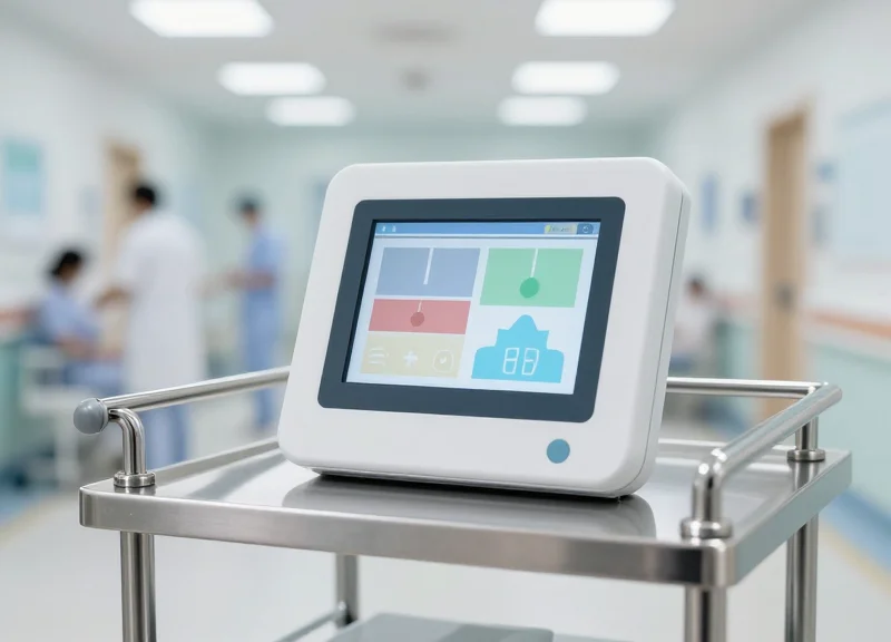
Integrating RFID data into a Manufacturing Execution System (MES) is the critical process of bridging the gap between the physical floor and the digital record. In high-stakes automotive assembly, this integration ensures that the 'Digital Birth Certificate' of a vehicle is updated in real-time. By connecting RFID readers directly to the MES via middleware or industrial protocols like OPC UA, the factory creates a fail-safe environment where the machine logic knows exactly which components are present before a single bolt is tightened.
- Data Acquisition at the Edge: RFID readers stationed at the marriage station capture the unique Tag ID (TID) from both the engine and the gearbox as they enter the assembly zone.
- Middleware Filtering and Aggregation: A middleware layer cleans the raw signal, removing duplicate reads and ghost signals, ensuring only valid component data is passed to the enterprise network.
- MES Logic Validation: The MES receives the component IDs and cross-references them against the specific Vehicle Identification Number (VIN) build order to confirm the gear ratio and torque specifications match.
- Actionable Interlock Trigger: If the IDs match the build order, the MES sends a 'Go' signal to the Programmable Logic Controller (PLC) to proceed; if they mismatch, the line is automatically locked to prevent a $50k recall event.
| Data Element | MES Function | Strategic Value |
|---|---|---|
| RFID Tag UID | Component Serialization | Ensures 1:1 traceability for every part installed. |
| Timestamp Data | Cycle Time Analysis | Identifies bottlenecks in the marriage process. |
| Reader Location ID | WIP Tracking | Provides real-time visibility of inventory on the line. |
| Validation Status | Quality Gatekeeping | Automatically prevents the assembly of mismatched units. |
Expert Insight: To truly eliminate the risk of a $50,000 recall, plants must move away from 'Polling' architectures toward 'Event-Driven' integration. In a polling setup, the MES asks the reader for data every second, which can create a latency gap. In an event-driven architecture, the RFID read triggers an immediate interrupt in the MES logic. This 'Sub-Second Interlock' ensures that the assembly line cannot physically move to the next stage until the MES has verified the component match, effectively making it impossible to build a mismatched unit even at high line speeds.
What happens if the MES connection goes down?
Robust integrations utilize 'Edge Buffering' where the RFID middleware stores validation logic locally. This allows the line to continue operating for a limited time using a local cache of the build schedule, syncing back to the main MES once connectivity is restored.
Does RFID integration require changing my existing PLC code?
Generally, no. Modern RFID systems use standard industrial protocols like EtherNet/IP or PROFINET, allowing them to act as standard I/O devices that communicate directly with the PLC while the MES handles the high-level data validation.
How do we handle 'Ghost Reads' from nearby components?
By implementing RSSI (Received Signal Strength Indicator) thresholds and shielding within the MES integration logic, the system can distinguish between the engine currently on the mount and one passing by on a secondary conveyor.
Future-Proofing: From Error-Proofing to Predictive Maintenance

Future-proofing in smart automotive plants involves leveraging the high-granularity data captured during RFID-driven assembly to create a permanent 'digital birth certificate' for every powertrain. While initial implementation focuses on error-proofing (Poka-yoke) to ensure the correct engine is paired with the correct gearbox, the real long-term ROI lies in transitioning this data into the service phase. By correlating factory-floor installation parameters with real-world performance, manufacturers can evolve from reactive fixes to predictive maintenance models that anticipate component failures before they trigger costly mass recalls.
| Feature | Legacy Error-Proofing | RFID-Driven Predictive Maintenance |
|---|---|---|
| Primary Goal | Prevent assembly mistakes | Optimize vehicle lifecycle & reliability |
| Data Duration | Transient (Session-based) | Permanent (Digital Twin) |
| Recall Scope | Broad/Batch-based | Surgical/Unit-specific |
| Feedback Loop | Immediate (Line stop) | Long-term (R&D and Service) |
The transition to predictive maintenance is built on the foundation of data lineage. When an engine and gearbox are matched via RFID, the system records not just the 'match,' but the specific environmental conditions, torque levels, and software versions at the moment of integration. This creates a high-fidelity record that can be analyzed against field data years later.
- Field-to-Factory Correlation: Linking specific component batch IDs (via RFID) to field failure rates allows engineers to pinpoint the exact manufacturing window of a defect.
- Automated Warranty Validation: Service centers can scan components to verify that the 'as-built' configuration matches the 'as-serviced' state, preventing fraudulent or incorrect warranty claims.
- Surgical Recall Execution: Instead of recalling 50,000 vehicles, manufacturers can identify the specific 450 units that utilized a compromised component batch during a specific shift.
The Veteran Perspective (Unique Insight): Most automotive manufacturers treat RFID data as 'exhaust'—a byproduct of production that is archived and forgotten. The true 'Silicon Valley' approach is to treat this data as 'fuel.' By applying machine learning to the specific assembly deviations recorded during the engine-gearbox matching process, we have seen cases where plants can predict which units will have higher vibration signatures (NVH issues) 36 months before the customer ever reports a problem. This is the difference between a brand that survives and a brand that leads.
How does this impact the secondary vehicle market?
A verifiable RFID-backed assembly history increases resale value by providing a 'Carfax for Components,' proving the integrity of the original powertrain matching.
Can this data be used for regulatory compliance?
Yes, it provides an immutable audit trail that satisfies ISO/IATF 16949 standards and various national safety board requirements for traceability.
Does this require constant cloud connectivity?
No. The RFID tag acts as a local data carrier, while the MES synchronizes the records to the cloud periodically for long-term fleet analytics.
DragonGuard Solutions: Specialized RFID for the Automotive Sector

DragonGuard Solutions offers a purpose-built ecosystem of RFID tags and readers designed specifically to withstand the rigors of the automotive powertrain assembly line. Unlike standard retail or logistics tags, DragonGuard's automotive series is engineered to maintain 100% data integrity in environments characterized by high-density metal, extreme thermal fluctuations, and exposure to industrial fluids. By focusing on specialized housing materials and advanced antenna tuning, DragonGuard ensures that the critical link between an engine and its corresponding gearbox is never lost due to hardware failure, directly mitigating the risk of $50,000-plus recall events.
| Feature | Commercial Grade RFID | DragonGuard Automotive Series |
|---|---|---|
| Max Operating Temperature | 70°C to 85°C | Up to 250°C (High-Temp Peaks) |
| Mounting Capability | Surface-only / Non-metal | On-Metal / Flush-mount in Steel |
| Chemical Resistance | Low (Plastic housing) | High (Oils, Coolants, Solvents) |
| Data Retention | Standard 10 years | Extended 30-50 years |
- Ceramic and PPS Encapsulation: Engineered for durability, these tags utilize Polyphenylene Sulfide (PPS) or specialized ceramics to prevent water ingress and chemical corrosion during engine washing or testing phases.
- Anti-Metal Interference Technology: Equipped with specialized ferrite layers, DragonGuard tags utilize the metallic surface of the engine block as an antenna extension rather than being suppressed by it, increasing read ranges in dense environments.
- Miniaturized Form Factors: Designed to fit into existing bolt holes or cast recesses on engine blocks and gearbox casings without requiring structural modifications.
Expert Insight: One critical differentiation for DragonGuard is our 'Thermal-Sync' antenna design. In automotive assembly, parts undergo rapid heating and cooling. Standard RFID tags often fail because the thermal expansion of the adhesive or casing snaps the internal chip-antenna bond. DragonGuard uses a proprietary floating-chip architecture that allows for microscopic expansion and contraction, ensuring that the tag remains functional throughout the entire lifecycle of the component, even after the vehicle leaves the factory.
Can these tags be used in the engine casting process?
Yes, specific DragonGuard high-temperature tags are designed to be embedded directly into the sand-casting or die-casting process, providing a 'birth record' that lasts the life of the part.
What is the typical read range in a high-EMI plant?
Despite electromagnetic interference from robotic welders and high-power motors, DragonGuard readers maintain a stable read range of 1 to 5 meters depending on the specific tag and environment configuration.
Do they support both HF and UHF protocols?
While we specialize in UHF (RAIN RFID) for long-range assembly tracking, we offer Dual-Frequency tags that combine NFC for easy technician maintenance via mobile devices with UHF for automated plant tracking.