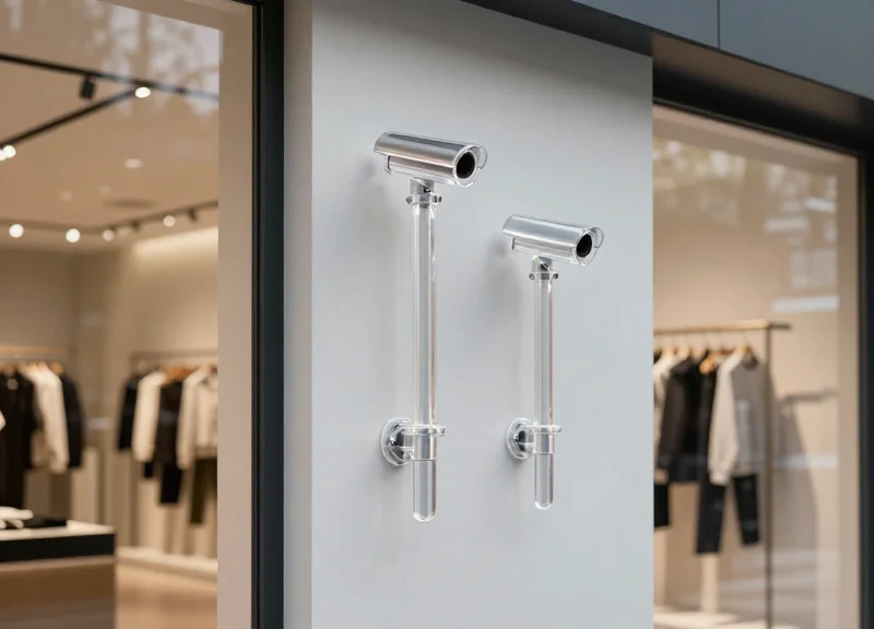
In high-traffic retail environments where the risk of theft is elevated, the physical and electronic integrity of your security entrance is paramount. Traditional EAS pedestals often fall short in high-loss zones due to physical wear or electronic interference. Reinforced aluminum EAS antennas provide a superior solution, combining structural durability with high-precision detection. However, the effectiveness of these systems depends heavily on technical execution. This guide outlines the essential technical strategies to ensure your DragonGuardGroup EAS system provides a reliable shield against shrinkage while maintaining a professional aesthetic.
The Strategic Importance of Reinforced Aluminum in Retail Security

In high-loss retail environments, reinforced aluminum is the strategic material of choice for Electronic Article Surveillance (EAS) antennas because it offers a critical 'Goldilocks' profile: the structural rigidity of metal combined with the electromagnetic neutrality required for signal clarity. Unlike traditional plastic housings that degrade under UV exposure or physical impact, or steel frames that can cause magnetic interference, reinforced aluminum protects internal sensitive electronics from the 'mechanical noise' and physical collisions common at high-traffic store entrances without shielding the Radio Frequency (RF) or Acousto-Magnetic (AM) fields necessary for theft detection.
| Feature | Reinforced Aluminum | Standard ABS Plastic | Stainless Steel |
|---|---|---|---|
| Impact Resistance | High (Shatter-proof) | Low (Brittle over time) | Very High |
| Signal Interference | Negligible (Non-ferrous) | None | High (Eddy Current risks) |
| Weight-to-Strength | Superior | Poor | Heavy/Difficult install |
| Aesthetic Life | 10+ Years (Anodized) | 3-5 Years (Yellowing) | 8+ Years |
From a technical engineering perspective, the use of reinforced aluminum addresses a common failure point in retail security: the 'Deformation Alarm.' Modern EAS systems utilize high-gain Digital Signal Processing (DSP) to detect tags at wider distances. Even a millimeter of flex in an antenna housing caused by a customer leaning on it or a shopping cart strike can shift the internal copper windings, changing the inductance and triggering a 'phantom alarm.' Reinforced aluminum frames provide the dimensional stability required to keep these sensitive internal components perfectly calibrated, ensuring a lower False Alarm Rate (FAR) and higher staff confidence.
- The Silicon Valley Perspective: Signal-to-Noise Ratio (SNR) Stability: Expert Tip: While most retailers focus on the 'look' of aluminum, the real value lies in SNR stability. Anodized aluminum acts as a natural heatsink for the internal transmitters, preventing thermal drift in the oscillator circuits during peak store hours. This ensures that the detection sensitivity remains constant from opening to closing, regardless of environmental temperature fluctuations.
- Total Cost of Ownership (TCO) Advantage: While the initial capital expenditure for aluminum-housed antennas is 15-20% higher than plastic, the TCO over a 5-year period is significantly lower due to the elimination of housing cracks, hinge failures, and the reduced need for recalibration service calls.
Does aluminum interfere with RF/AM signals?
No, because it is non-ferrous. However, the design must avoid 'closed loops' in the frame construction to prevent eddy currents, which is why professional reinforced antennas use insulated junctions.
How does it perform in 'High-Loss' zones specifically?
In high-theft areas, perpetrators often attempt to disable antennas via physical force. Aluminum's tensile strength prevents internal component exposure, maintaining the deterrent effect even after an attempted vandalism event.
Conducting a Comprehensive Electromagnetic Site Survey

A comprehensive electromagnetic site survey is a specialized technical audit performed to identify, measure, and map environmental noise and interference that could compromise the efficacy of EAS systems. In high-loss retail zones, where reinforced aluminum antennas are deployed for their superior durability and passive shielding properties, the survey acts as the 'blueprint' for calibration. By detecting noise sources like LED drivers, automatic doors, and digital signage before bolting hardware to the floor, technicians can adjust the system’s sensitivity thresholds to prevent false alarms—commonly known as 'ghosting'—while maintaining high detection rates for tagged items.
- Baseline Ambient Noise Mapping: Utilize a spectrum analyzer or the EAS system’s built-in diagnostic software to measure the RFI/EMI floor levels during standard business hours when all mall or building electronics are active.
- Dynamic Load Testing: Monitor signal fluctuations while cycling high-draw equipment, such as HVAC systems or motorized shutters, to identify transient interference spikes that only occur at specific intervals.
- Inductive Loop Identification: Check for hidden floor rebars or metal door frames that could create an inductive loop, potentially distorting the antenna’s magnetic field and creating 'blind spots' in the detection zone.
| Noise Level (mVRMS) | Impact Level | Technical Mitigation Strategy |
|---|---|---|
| 0 - 40mVRMS | Low Noise | Standard calibration; passive shielding of reinforced aluminum is sufficient. |
| 40 - 100mVRMS | Moderate Interference | Requires software-side filtering and potential phase adjustment between pedestals. |
| 100mVRMS + | Critical/High-Loss Zone | Physical relocation of antenna or installation of active ferrite chokes on power lines. |
Expert Insight: The 'Shadow Interference' Effect. Many installers overlook the impact of modern LED lighting arrays. While aluminum housings provide excellent protection against lateral RFI, 'Shadow Interference' can leak through the top or bottom of the pedestal. My advice: always perform a 360-degree sweep with a handheld sniffer at the exact height of the proposed antenna’s top coil. If you detect high-frequency switching noise from ceiling-mounted LEDs, you may need to specify top-shielded aluminum enclosures, a detail often missed in generic installations.
Why can't I just rely on the antenna's 'Auto-Tune' feature?
Auto-tune manages internal impedance but cannot distinguish between a shoplifter's tag and a 'dirty' power signal from a neighboring store's neon sign. A site survey identifies the source, allowing for physical mitigation.
What equipment is essential for a high-loss zone survey?
Beyond basic diagnostic software, a professional-grade spectrum analyzer and an oscilloscope are essential for visualizing 'burst noise' that software-only tools often miss.
Does the reinforced aluminum housing affect the survey results?
Yes. The aluminum acts as a Faraday shield for the electronics inside. Your survey must account for the difference between the noise levels outside the housing versus what the internal receiver 'sees'.
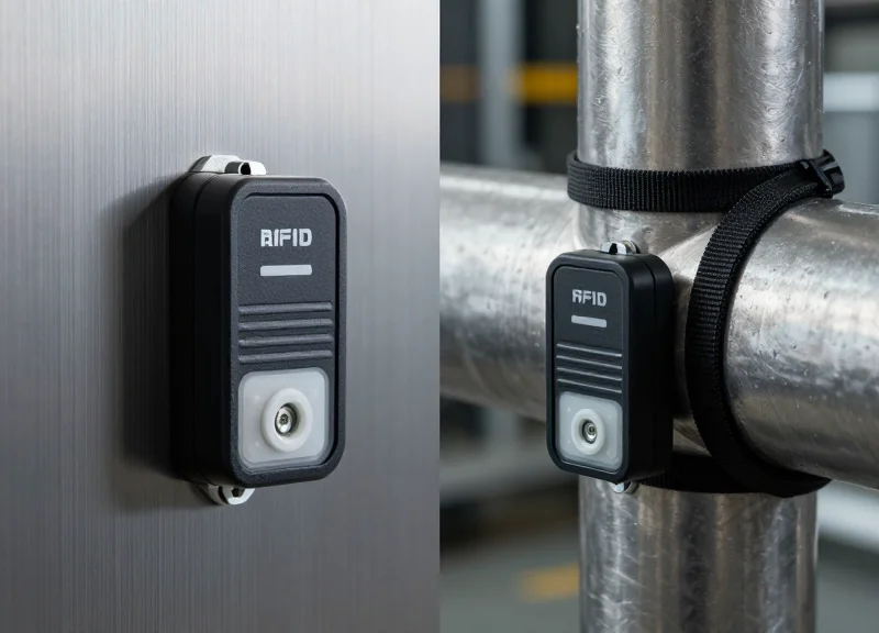
Precision Anchoring: Securing the Pedestal for Longevity
Precision anchoring is the technical process of fixating an EAS antenna to a substrate using industrial-grade fasteners to ensure the system remains plumb and functional under mechanical stress. For reinforced aluminum antennas—which are heavier and more rigid than plastic alternatives—anchoring must account for the high-leverage forces generated during accidental impacts from shopping carts or floor scrubbers, effectively transferring kinetic energy into the concrete slab rather than the antenna frame.
| Anchor Type | Substrate Material | Pull-Out Strength | Impact Resistance |
|---|---|---|---|
| Wedge Anchors | Solid Concrete | High | Excellent |
| Chemical/Epoxy | Aged/Fractured Concrete | Maximum | Superior |
| Sleeve Anchors | Brick or Block | Medium | Moderate |
| Toggle Bolts | Raised Wood Floors | Low | Poor |
- Substrate Verification: Before drilling, use a GPR (Ground Penetrating Radar) or a high-quality stud finder to identify rebar, post-tension cables, or electrical conduits embedded in the floor.
- Template Alignment: Utilize the reinforced aluminum base plate as a physical template to mark drilling points, ensuring a minimum 150mm clearance from the door's sweep radius.
- Bore Hole Preparation: Drill to the specified depth and use a vacuum or compressed air to remove all dust; residual debris can reduce anchor holding power by up to 50%.
- Fastener Torque: Set anchors and use a calibrated torque wrench to meet the manufacturer's exact specifications, preventing stress fractures in the aluminum flange.
Expert Insight: The Isolation Gasket Technique. In high-loss zones, aluminum antennas often fail not from the metal snapping, but from 'base-grind' against uneven concrete. I recommend installing a 3mm high-density neoprene gasket between the aluminum base and the floor. This act of 'decoupling' the antenna from the rigid slab provides a dampening effect that absorbs high-frequency vibrations and impact shocks, significantly extending the life of the internal electronics and preventing the anchors from backing out over time.
How do I prevent floor tiles from cracking during installation?
Always use a diamond-tipped core bit to drill through the ceramic or porcelain layer without impact, then switch to a masonry hammer bit for the concrete slab below.
Should I use stainless steel or galvanized anchors?
Stainless steel (Grade 304 or 316) is mandatory for aluminum antennas to prevent galvanic corrosion, which occurs when dissimilar metals react with moisture near retail entrances.
What is the minimum embedment depth for high-impact zones?
For reinforced aluminum systems, a minimum embedment of 3 inches (75mm) into 3000 PSI concrete is required to withstand typical shopping cart collisions.
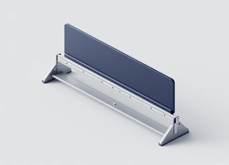
Optimal Pedestal Spacing and Detection Geometry

Optimal pedestal spacing is the calculated maximum distance between two EAS antennas that ensures a 95% or higher detection rate of active security tags while maintaining a stable signal-to-noise ratio. In high-loss zones, this distance typically ranges from 1.2 to 2.4 meters, depending heavily on whether the system operates on Acousto-Magnetic (AM 58kHz) or Radio Frequency (RF 8.2MHz) technology and the physical orientation of the detection field's geometry.
| Technology Type | Typical Tag Type | Recommended Spacing (Meters) | Detection Geometry Focus |
|---|---|---|---|
| AM (58kHz) | DR Labels / Pencil Tags | 1.4m - 2.0m | Vertical & Lateral 3D Field |
| RF (8.2MHz) | Paper Labels / Hard Tags | 1.2m - 1.8m | Center-field Peak Density |
| Advanced AM (Reinforced) | Large Hard Tags | Up to 2.4m | Extended Perimeter Detection |
Expert Insight: The Flux Compression Effect. Unlike standard plastic pedestals, reinforced aluminum frames act as a secondary 'passive' shield. While this protects the internal electronics from external interference, it can slightly compress the magnetic flux lines. This means that while your detection field is more robust and less prone to 'jitter' from nearby metal objects, you must calibrate for a narrower but more intense 'sweet spot.' We recommend reducing the manufacturer’s 'lab-tested' spacing by 10% in high-loss retail environments to account for this compression and ensure 100% catch rates at the very top and bottom of the detection zone.
- Identify the 'Smallest Common Denominator' Tag: Base your spacing calculations on the smallest, least-sensitive tag used in your store (typically soft labels) rather than high-performance hard tags.
- Map the 3D Detection Volume: EAS fields are not flat; they are volumetric. Test detection at floor level, waist height, and shoulder height to ensure no 'dead zones' exist due to the aluminum frame's shielding.
- Account for Metal-Free Zones: Maintain a minimum 'clean' radius of 0.5 meters from large metal objects like door frames or HVAC ducts to prevent field distortion.
Can I install antennas wider than the recommended spacing?
You can, but detection rates will drop exponentially. For every 10cm beyond the optimal limit, detection sensitivity can decrease by up to 20% in high-noise environments.
How does aluminum affect the 'Phantom Alarm' rate?
Reinforced aluminum pedestals actually reduce phantom alarms. The rigid housing minimizes vibration-induced interference (microphonics) which is common in flimsy plastic units.
Should antennas be perfectly parallel?
Yes. Even a 5-degree tilt in detection geometry can create a 'blind wedge' at the top of the entrance where professional shoplifters are known to carry boosted bags.
Advanced Grounding and Power Filtration Techniques
Advanced grounding and power filtration are the bedrock of Electronic Article Surveillance (EAS) stability, designed to isolate the system's sensitive receiver from 'dirty power' and electromagnetic interference (EMI). In high-loss zones, where electrical noise from LED lighting, POS terminals, and HVAC systems can trigger phantom alarms, a dedicated grounding circuit ensures that the reinforced aluminum chassis acts as a shield rather than an accidental antenna. By maintaining a clean signal-to-noise ratio (SNR), technicians can calibrate antennas to higher sensitivity levels without the risk of false positives.
| Feature | Standard Commercial Power | Optimized EAS Power Configuration |
|---|---|---|
| Circuit Type | Shared with other appliances | Dedicated 15A/20A isolated circuit |
| Grounding | Common building ground | Isolated Equipotential Grounding |
| Filtration | Basic surge protection | EMF/RFI Active Line Filtering |
| Voltage Variance | Fluctuates based on load | Regulated/Stabilized via Transformer |
- Establish a Dedicated Power Line: Run a home-run circuit directly from the main distribution panel to the EAS pedestals. Avoid daisy-chaining with neon signs, motorized doors, or refrigeration units that generate high-frequency switching noise.
- Implement an Isolation Transformer: Use a 1:1 isolation transformer near the pedestal. This physically separates the EAS power supply from the building’s neutral-to-ground bonds, effectively 'cleaning' the power before it hits the electronics.
- Verify Equipotential Grounding: Ensure all metal components—the reinforced aluminum frame, internal electronics, and floor anchors—are bonded to the same ground potential to prevent 'ground loops' that manifest as low-frequency hum.
- Install Ferrite Cores on Data Cables: Snap high-permeability ferrite beads onto both ends of the synchronization and power cables to suppress common-mode noise that travels along the exterior of the wire shielding.
### The Aluminum Shielding Paradox: An Expert Insight While reinforced aluminum pedestals provide superior structural integrity, they present a unique electrical challenge: the skin effect. At high frequencies (like the 58kHz or 8.2MHz used in EAS), noise can travel along the surface of the aluminum housing. If the housing is not properly grounded using a low-impedance copper strap (rather than just a standard wire), the pedestal itself can become a 'parasitic radiator'—re-broadcasting environmental noise directly into the internal receiver. Always use a braided grounding strap for the best high-frequency performance.
Why are my antennas alarming every time the automatic door opens?
This is likely due to 'conducted EMI.' The door motor sends a noise spike through the shared power line. Installing a dedicated circuit or an active power filter usually resolves this instantly.
Can I use a standard UPS for my EAS system?
Only if it is an 'Online Double Conversion' UPS. Basic 'Standby' or 'Line-Interactive' UPS units do not provide the necessary galvanic isolation or pure sine wave output required for high-sensitivity EAS tuning.
Does the length of the ground wire matter?
Yes. Keep ground leads as short as possible. Longer wires have higher inductance, which reduces their effectiveness at draining high-frequency interference away from the antenna.
Multi-System Synchronization for Seamless Coverage

Multi-system synchronization is the process of aligning the transmission bursts of two or more EAS antennas so they operate on a unified temporal and phase frequency. In high-loss zones with wide entrances, failing to synchronize antennas leads to signal phase cancellation—a phenomenon where overlapping radio waves from adjacent pedestals effectively 'cancel' each other out, creating invisible blind spots where shoplifters can pass tagged items undetected.
When using reinforced aluminum pedestals, synchronization becomes even more critical. Aluminum's high conductivity can cause minor signal reflections (multipath interference) that shift the phase of the signal. If your antennas are 'fighting' each other rather than working in concert, you lose the detection depth required for high-risk inventory.
| Synchronization Method | Best Use Case | Key Advantage |
|---|---|---|
| Hard-Wired Sync | Permanent installations with under-floor conduit. | Highest reliability; immune to power line noise. |
| Power Line Communication (PLC) | Retrofit environments where new cabling is impossible. | Uses existing AC wiring to sync pulse timing. |
| Wireless RF Sync | Open-concept stores with minimal infrastructure. | Fastest installation; requires clear line-of-sight. |
- Identify the Master Controller: Designate the most centrally located or stable pedestal as the 'Master' to provide the primary clock signal for all 'Slave' units.
- Set Phase Delay Offsets: Adjust the phase (typically in 90-degree increments) on adjacent pedestals to ensure the magnetic fields are additive rather than subtractive.
- Configure Burst Frequency: Ensure all units are pulsing at the exact same rate (e.g., 58kHz for Acousto-Magnetic systems) to prevent 'beat frequencies' that cause false alarms.
- Validate with a Field Strength Meter: Use a specialized meter to walk the entrance and verify there are no 'dead zones' where signal strength drops below detection thresholds.
Expert Tip: The 'Aluminum Multipath' Compensation. Because reinforced aluminum is more reflective than plastic, I recommend setting a 5-10 microsecond 'Phase Buffer' when installing in metallic environments. This slight delay compensates for the time it takes for signals to bounce off the pedestal frames, preventing the system from misinterpreting its own reflections as a tag signal.
What is 'Ghosting' in EAS systems?
Ghosting occurs when unsynchronized antennas create false triggers or random alarms because the receiver in one pedestal picks up the unsynced transmission burst from another.
Can I sync antennas from different manufacturers?
Generally, no. Synchronization protocols are usually proprietary. For seamless coverage, it is standard practice to use the same logic boards across all pedestals in a single entrance.
How does synchronization affect detection width?
Properly synced antennas allow for a wider 'detection corridor' (up to 2.4 meters or more) because the combined signal strength is maximized at the center point between pedestals.
Fine-Tuning Sensitivity and Threshold Settings
Fine-tuning sensitivity and threshold settings is the critical software-side process of calibrating an Electronic Article Surveillance (EAS) system to distinguish between a genuine security tag and background electromagnetic interference. In high-loss zones, where reinforced aluminum antennas are often subjected to heavy metallic traffic and nearby digital displays, achieving a high Signal-to-Noise Ratio (SNR) is the difference between a secure entrance and a constant source of 'ghosting' false alarms. This phase involves using proprietary diagnostic software to set the 'Gate' level—the point at which the system decides a signal is a threat rather than environmental static.
| Parameter | Function | Impact of Incorrect Setting |
|---|---|---|
| Sensitivity (Gain) | Determines how 'hard' the antenna listens for signals. | Too high: Frequent false alarms; Too low: Missed detections. |
| Threshold | The minimum signal strength required to trigger an alarm. | Too high: Tags go undetected; Too low: System triggers on minor EMI spikes. |
| Phase Filtering | Filters signals based on the timing of the response. | Incorrect settings cause detection dead zones in wide aisles. |
- Establish the Noise Floor: Before introducing any tags, run a background noise diagnostic to identify the ambient EMI levels. This provides a baseline for setting your threshold safely above the 'noise floor'.
- Dynamic Sensitivity Adjustment: Increase sensitivity incrementally while passing a standard security tag through the center of the aisle until a consistent 95-100% detection rate is achieved.
- Threshold Masking: Set the threshold slightly above the highest recurring noise spike. This 'masks' random environmental interference without sacrificing the signal strength of a legitimate tag.
- Validation Under Load: Test the system during peak hours. High-loss zones often see increased noise when nearby automatic doors and POS systems are in heavy use.
Expert Insight: Temporal Signature Analysis While most technicians only look at signal amplitude (strength), veteran engineers look at the temporal signature. Modern reinforced aluminum systems allow you to filter signals based on the pulse duration. A security tag has a very specific decay rate when it resonates; electrical noise from a nearby neon sign or a motor does not. By tightening the pulse-width window in the software, you can effectively ignore massive amounts of EMI that would otherwise force you to lower your sensitivity to ineffective levels.
What is 'ghosting' in EAS systems?
Ghosting refers to false alarms triggered by environmental factors like metal shopping carts, overhead lighting, or nearby electronics that mimic the frequency of a security tag.
How does the aluminum frame affect tuning?
Reinforced aluminum is highly conductive. If not properly grounded and tuned, the frame itself can create eddy currents that the software must be taught to ignore via phase-shifting adjustments.
How often should settings be re-evaluated?
Recalibration should occur bi-annually or whenever the store layout changes, as shifting metal fixtures or new electronic displays will inevitably alter the EMI landscape.
Cable Management and Concealment for Durability

In high-traffic retail environments, cable failure is the leading cause of EAS system downtime. Durable cable management for reinforced aluminum antennas involves routing power and data lines through protective conduits—ideally embedded within the floor slab—to shield them from the constant mechanical vibration of shopping carts, heavy foot traffic, and industrial floor scrubbers. By concealing these connections, you not only prevent accidental disconnection and physical fraying but also mitigate electromagnetic interference (EMI) that can trigger false alarms.
| Routing Method | Durability Level | Best Use Case | Key Advantage |
|---|---|---|---|
| In-Floor Trenching | Maximum | New construction or major remodels | Total immunity to surface impacts and theft tampering. |
| Surface-Mount Raceways | Moderate | Retrofitting existing storefronts | Easier access for future maintenance or upgrades. |
| Under-Carpet Flat Cables | Low | Low-traffic boutique entrances | Minimal aesthetic impact with zero floor cutting. |
To ensure your reinforced antennas remain operational, follow these technical best practices for routing and securing the wiring infrastructure.
- Specify Liquid-Tight Flexible Conduit: In zones where floor cleaning involves heavy moisture, use liquid-tight conduits (LFMC) to prevent water ingress into the antenna base, which can corrode terminals over time.
- Implement the 'Service Loop' Technique: Leave an extra 12-18 inches of slack inside the antenna base. This 'service loop' prevents cable tension if the reinforced antenna is bumped or slightly shifted by a heavy impact, acting as a shock absorber for the electrical connections.
- Separate High-Voltage and Data Lines: Maintain a minimum 4-inch separation between AC power lines and EAS data cables within the floor to prevent signal crosstalk that degrades detection sensitivity.
Expert Tip: I recommend using 'Sacrificial Pigtails' for high-loss zones. By using a short, replaceable jumper cable between the main floor-run and the antenna's internal board, you ensure that any severe physical impact that tears a cable only destroys a $10 jumper rather than requiring a multi-thousand dollar floor-trenching repair.
What cable grade is required for high-loss EAS zones?
Always use shielded twisted pair (STP) Category 6 or higher for data. The shielding is critical in high-loss zones to block interference from nearby neon signs or large LED displays.
How deep should in-floor conduits be buried?
Conduits should be buried at least 1.5 to 2 inches below the surface of the concrete to avoid cracking the slab under the weight of heavy pallet jacks.
Should I use metal or plastic raceways for surface mounting?
In high-loss zones, use heavy-duty steel raceways. Plastic versions can be easily crushed by heavy carts, exposing the wires to damage and potential tampering by shoplifters.
Post-Installation Testing Protocols
Post-installation testing for reinforced aluminum EAS antennas is the formal process of validating the electromagnetic field's integrity across the entire entrance. Unlike basic 'walk-through' tests, a professional protocol involves mapping the detection zone in three dimensions—height, width, and depth—using various tag orientations to ensure that 'dead zones' are eliminated and the system achieves its maximum theoretical detection rate in high-loss environments.
| Test Parameter | Target Metric | Verification Method |
|---|---|---|
| Detection Height | Up to 1.5 meters | Vertical sweep at 30cm increments |
| Orientation Sensitivity | 99.9% Tag Pick-up | Testing tags in X, Y, and Z axes |
| Dead Zone Mapping | Zero blind spots | Slow-motion floor-level sweep |
| External Noise | < 15% SNR | Software diagnostic noise floor check |
- The 3-Axis Orientation Test: Hold the EAS tag in three distinct positions: parallel to the antenna, perpendicular, and at a 45-degree angle. High-loss zones often suffer from signal nulls where tags are invisible if held flat; this test identifies if antenna phasing needs adjustment.
- The 'Slow Walk' Boundary Check: Move through the pedestals at a pace of 0.5 meters per second. Fast walking can sometimes bypass a system with slow processing cycles. This ensures the digital signal processor (DSP) captures the tag signature even at the perimeter of the field.
- Multi-Tag Collision Testing: Carry multiple tags through the entrance simultaneously. This verifies the system's ability to distinguish between distinct signals and ensures the alarm triggers even when 'signal masking' techniques are attempted.
- Interference Stress Test: Activate nearby electronic equipment (LED displays, automatic doors) during testing to ensure that environmental noise does not cause false alarms or desensitize the receivers.
Expert Insight: Implement the 'Dynamic Shadow' test. In high-traffic zones, the human body acts as a significant attenuator of RF/AM signals. Perform your final testing with a 'human shield'—have a second person walk closely between the tag and the antenna. If the system fails to detect the tag when shielded by body mass, you must increase the gain or adjust the synchronization to compensate for this real-world density.
Why does the system alarm when no one is passing?
This is usually caused by 'phantom' interference from nearby power cables or loop loops in metallic structures (like metal door frames) that have become energized. Re-check the grounding and filtration settings.
What should I do if there is a dead zone at the very center of the entrance?
This indicates a phase cancellation issue. Adjust the 'Sync' settings in your software to shift the pulse timing, ensuring the waves from the two antennas do not cancel each other out.
How often should these protocols be repeated?
We recommend a full technical re-validation every 6 months or whenever the storefront layout (especially metal fixtures) is significantly changed.