In the modern retail landscape, aesthetic store design often clashes with security requirements. Overhead Electronic Article Surveillance (EAS) sensors offer a discreet, ceiling-mounted solution that preserves open entrances, yet they face a significant technical hurdle: Electromagnetic Interference (EMI). High-EMI zones, packed with LED displays, escalators, and automated doors, often trigger 'phantom alarms' that frustrate customers and desensitize staff. This technical blueprint provides a comprehensive guide to calibrating next-gen overhead EAS sensors, ensuring maximum detection accuracy while effectively silencing environmental noise.
The Evolution of Overhead EAS in High-Traffic Retail
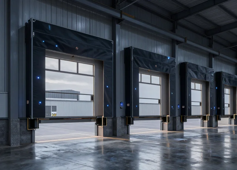
Overhead Electronic Article Surveillance (EAS) represents a significant paradigm shift in retail loss prevention, moving from visible physical barriers to 'invisible' protection zones. Unlike traditional pedestals that create a narrow 3-to-6-foot corridor at store entrances, next-gen overhead sensors utilize ceiling-mounted RFID or Acousto-Magnetic (AM) antennas to monitor wide-open egress points. This evolution is driven by the retail industry's move toward 'Open Store' concepts and omnichannel fulfillment, where removing physical friction is paramount to the customer experience. However, moving the sensor 10 feet above the floor introduces complex physics challenges, requiring a leap from simple proximity detection to advanced spatial signal processing.
| Feature | Legacy Pedestal Systems | Next-Gen Overhead Sensors |
|---|---|---|
| Aesthetics | Obtrusive physical barriers. | Invisible/Ceiling-integrated. |
| Traffic Flow | Creates bottlenecks at entrances. | Enables wide, open-concept egress. |
| Detection Zone | Horizontal proximity (2D). | 3D Volumetric surveillance. |
| EMI Vulnerability | Low (closer to tags). | High (distance increases noise ratio). |
One critical technical hurdle in this evolution is the 'Inverse Square Law' of signal propagation. In a standard pedestal setup, the distance between the tag and the antenna is usually less than three feet. When sensors are moved to the ceiling (10+ feet), the signal strength of the responding tag drops exponentially. To compensate, overhead systems must operate with much higher sensitivity thresholds. This makes them significantly more susceptible to Electro-Magnetic Interference (EMI) from LED lighting drivers, digital signage, and HVAC controllers—common fixtures in modern high-traffic retail environments that were rarely a concern for legacy systems.
Why is EMI a bigger problem for overhead systems than pedestals?
Because overhead sensors are further from the tags, they must be tuned to detect much weaker signals. This heightened sensitivity means that ambient electronic noise, which a pedestal would ignore, is often misinterpreted as a tag signal by overhead units.
Does 'Invisible' security impact theft rates?
While pedestals act as a visual deterrent, overhead systems often lead to more 'natural' shopping behavior. Strategic retailers use 'Soft Deterrence' like digital signage or audio alerts to compensate for the loss of physical pedestals.
Can legacy AM tags be used with overhead systems?
Yes, but with caveats. Traditional tags are often optimized for vertical orientation; overhead sensors require high-performance labels or specific 3D-oriented tags to ensure consistent detection from 10 feet away.
Identifying EMI Hotspots: The Physics of False Alarms

An EMI hotspot is a localized zone within a retail environment where ambient electromagnetic noise—generated by electrical systems, lighting, or machinery—reaches an amplitude and frequency that overlaps with the operational band of Electronic Article Surveillance (EAS) sensors. In the context of overhead Acousto-Magnetic (AM) systems, these hotspots typically occur near 58kHz. Unlike floor-based pedestals that primarily monitor horizontal signals, overhead sensors are uniquely vulnerable to vertical noise vectors originating from ceiling-mounted infrastructure, where 'near-field' coupling can cause the system to misinterpret background interference as a legitimate tag signal.
| Noise Source | Physical Mechanism | EAS Impact Level |
|---|---|---|
| Switching Power Supplies | Conducted/Radiated EMI (20-150kHz) | Critical (Direct AM overlap) |
| Dimmable LED Drivers | High-frequency PWM harmonics | High (Intermittent jitter) |
| HVAC Variable Speed Drives | Broadband pulse-width modulation | Medium (Sync issues) |
| Metal Structural Loops | Passive re-radiation/Resonance | High (Geometric ghosting) |
The fundamental physics of these alarms is rooted in the Signal-to-Noise Ratio (SNR). Overhead sensors use high-gain receivers to detect tags from heights of up to 4 meters; however, this increased sensitivity also captures 'far-field' radiated emissions that pedestals would ignore. A unique challenge for modern retail is the Structural Antenna Effect. In many high-end retail designs, large metal frames, decorative aluminum slats, or HVAC ducting can act as passive antennas. These structures pick up low-frequency noise from the building's main electrical risers and re-radiate it directly into the overhead sensor's detection lobe, creating a 'ghost' signal that defies traditional shielding methods.
Why do LED lights trigger overhead EAS alarms?
Inexpensive or aging LED drivers utilize high-frequency switching to manage power. These drivers often produce harmonics that match the 58kHz resonance of AM tags. Because overhead sensors are physically closer to these drivers than floor pedestals, the 'noise floor' rises significantly, causing the sensor to trigger.
What is the difference between Conducted and Radiated noise?
Conducted noise travels through the AC power lines and enters the EAS system via the plug, while Radiated noise travels through the air as electromagnetic waves. Overhead sensors are particularly susceptible to Radiated noise from ceiling-mounted digital signage and neon transformers.
Can building structural steel cause false alarms?
Yes. Through a process called 'Inductive Coupling,' the metal infrastructure of a building can form a large loop that captures electromagnetic energy. If the EAS sensor's phase isn't correctly calibrated to ignore these environmental loops, it will continuously report high background noise.
Expert Insight: In my 20 years of field engineering, I have found that the most elusive 'hotspots' are often caused by 'Multipath Interference.' This occurs when a noise source reflects off metal surfaces—like elevator shafts or security gates—creating constructive interference at the sensor's location. When calibrating overhead systems, you must map the 3D volume of the entrance, not just the floor area, to identify where these reflected waves peak.
Pre-Calibration Site Survey: Mapping the RF Environment

A pre-calibration site survey is a systematic diagnostic assessment designed to map the radio frequency (RF) and electromagnetic landscape of a retail space before hardware installation. By utilizing high-precision spectrum analyzers and dedicated EAS diagnostic software, engineers can identify 'noise floors'—the level of background interference—and pinpoint specific frequencies that may trigger false alarms. In high-EMI zones, this survey serves as the foundation for the entire calibration strategy, transforming invisible interference into a visual heatmap of the store's electronic health.
- Baseline Ambient Sweep: Deactivate all non-essential electronics and use a spectrum analyzer to record the natural RF noise floor at the 58kHz (Acousto-Magnetic) or 8.2MHz (RF) bands.
- Active Load Testing: Systematically power on HVAC systems, LED lighting arrays, and digital signage to observe spike patterns in electromagnetic interference (EMI).
- Spatial Heatmapping: Walk the planned sensor coverage zone in a grid pattern, measuring signal-to-noise ratios (SNR) at 0.5-meter intervals to identify 'hot zones' near structural pillars or hidden wiring.
- Temporal Analysis: Conduct sweeps at different times of day to account for external factors like neighboring business operations or municipal power grid fluctuations.
| Interference Source | Typical Frequency Impact | Mitigation Threshold |
|---|---|---|
| LED Driver Arrays | Broadband (30kHz - 300kHz) | <-65 dBm |
| Switching Power Supplies | Variable Harmonics | <-70 dBm |
| VFDs (Motor Drives) | Low-frequency Pulsing | <-60 dBm |
| Digital Display Walls | High-frequency Noise | <-75 dBm |
Expert Insight: The 'Ghosting' Harmonic Phenomenon. While many engineers focus exclusively on the 58kHz center frequency, seasoned experts look for the 3rd and 5th harmonics of the local power grid (180Hz/300Hz). In modern LEED-certified buildings, high-efficiency lighting controllers often create harmonic oscillations that 'ghost' the pulsing rhythm of an EAS tag. If your survey detects rhythmic pulsing at these intervals, hardware-level filtering is mandatory, as software-only calibration will likely result in suppressed detection range.
Can I use a smartphone app for the RF survey?
No. Consumer smartphones lack the specialized antennas and sensitivity required to detect the low-frequency AM (58kHz) or high-frequency RF (8.2MHz) nuances needed for EAS calibration. Professional-grade spectrum analyzers or SDR (Software Defined Radio) kits are required.
What is a 'safe' noise floor for overhead sensors?
Ideally, the noise floor should be at least 15dB to 20dB below the peak signal of your test tag. Anything less than a 10dB margin significantly increases the risk of false positives in high-traffic zones.
Why map the environment before the sensors arrive?
Mapping early allows for structural remediation—such as shielding conduits or relocating neon signs—which is significantly cheaper than attempting to calibrate around a severe EMI source after the overhead units are mounted.
Advanced Digital Signal Processing (DSP) Configuration
Advanced Digital Signal Processing (DSP) configuration in overhead EAS sensors is the process of mathematically filtering raw radio frequency (RF) or acousto-magnetic (AM) data to distinguish between the unique harmonic signature of a security tag and 'false' triggers caused by ambient noise. By adjusting algorithms such as Fast Fourier Transforms (FFT) and temporal correlation, technicians can create a high-fidelity filter that maintains detection sensitivity while ignoring high-frequency bursts from LED drivers, point-of-sale terminals, and nearby escalators.
| DSP Parameter | Target Interference | Technical Adjustment |
|---|---|---|
| Bandpass Filtering | Wide-band RF Noise | Narrow the Q-factor to focus strictly on the 58kHz or 8.2MHz center frequency. |
| Dynamic Thresholding | Ambient Floor Fluctuations | Enable Automatic Gain Control (AGC) with a 200ms smoothing window. |
| Notch Filtering | Specific Device EMI (e.g., 60Hz) | Apply deep attenuation at specific fixed frequencies identified during the site survey. |
| Pulse Width Validation | Short Burst Transients | Increase minimum signal duration requirements to >1.5ms to filter out sparking. |
- Establish the Digital Noise Floor: Monitor the sensor's raw signal input with no tags present. Use the DSP software to set the baseline sensitivity 3dB above the highest observed periodic noise spikes.
- Apply Temporal Correlation: Configure the algorithm to require three consecutive 'valid' tag hits within a 100ms window before triggering an alarm, effectively eliminating random atmospheric noise.
- Optimize Phase-Shift Detection: Adjust the phase window to focus on the 90-degree phase shift typical of resonance tags, which helps differentiate them from linear reflections off metallic door frames.
Expert Insight: The 'Signature Decay' Validation. One of the most effective ways to outperform standard calibrations is to focus on the 'decay rate' of the signal. Unlike electronic interference which often cuts off instantly or remains constant, a physical EAS tag has a specific logarithmic decay as its resonance fades. By configuring your DSP to validate the 'envelope' of the signal decay rather than just the peak amplitude, you can virtually eliminate false alarms from LED ballasts and digital signage drivers that lack this specific physical property.
How does DSP handle moving metal interference?
Next-gen sensors use 'Motion Discrimination' algorithms that detect the Doppler shift of moving metal (like a shopping cart) and temporarily raise the detection threshold to avoid a false trigger.
Is it better to use Narrowband or Wideband DSP settings?
In high-EMI zones, Narrowband is superior as it rejects peripheral noise, though it requires more precise tag alignment.
What is the risk of over-filtering?
Aggressive DSP filtering can lead to 'blind spots' where genuine tags are ignored if their signal is slightly weakened by shielding or orientation.
Phase Tuning and Sensitivity Threshold Management
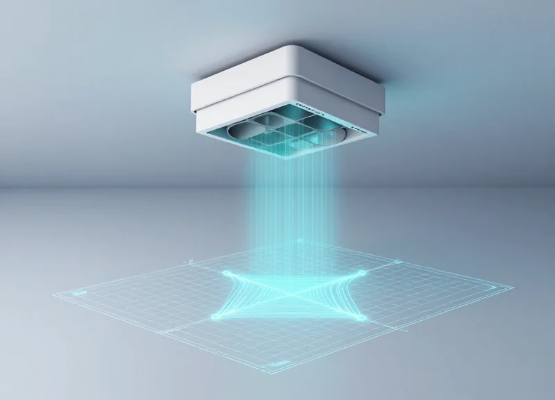
Phase tuning is the technical process of aligning an overhead EAS sensor's pulse-listening window with the environmental electromagnetic noise cycle to eliminate periodic interference, while sensitivity threshold management involves setting the precise signal-to-noise ratio (SNR) required to trigger an alarm without over-extending the detection range into adjacent high-noise areas. These two parameters define the 'detection bubble' geometry, ensuring the system ignores external EMI while maintaining 99% pick rates for tags passing directly beneath the antenna.
In high-EMI zones, such as retail environments near high-voltage lighting or automated doors, the overhead sensor must distinguish between the resonant frequency of an Acousto-Magnetic (AM) tag and the harmonics generated by electrical machinery. Phase tuning essentially acts as a 'temporal filter,' allowing the sensor to listen for tag echoes only during the quietest milliseconds of the electromagnetic cycle.
| Parameter | Setting Range | Impact on Performance | EMI Mitigation Level |
|---|---|---|---|
| Phase Angle | 0° - 359° | Shifts the listening window relative to AC mains cycle. | High: Eliminates synchronous noise. |
| Detection Sensitivity | 0 - 99 (Software Scale) | Controls the 'width' and 'depth' of the detection bubble. | Medium: Prevents 'phantom' alarms from far-field noise. |
| Tag Signal Filter | 1 - 10 (Intensity) | Determines how many consecutive pulses define a valid tag. | High: Filters out random RF bursts. |
- Identify the Noise Floor: With all tags removed from the area, use the diagnostic software to monitor the ambient noise floor. Target a steady-state noise level below 20% of the total signal capacity.
- Execute Phase Sweeping: Slowly rotate the phase angle while watching the noise amplitude. Find the 'Null Point' where the ambient noise from fixed electronics (like LED drivers) is at its absolute minimum.
- Establish the Sensitivity Ceiling: Increase the sensitivity gain until the system begins to 'self-alarm' or 'ring,' then back the setting off by 15-20% to create a safety buffer for environmental fluctuations.
- Define the Detection Bubble: Perform walk-tests at the perimeter of the desired zone. If the sensor triggers on tags in nearby checkout aisles, decrease sensitivity or adjust the antenna 'Q-factor' to tighten the field.
Expert Tip: The Zero-Crossing Alignment Technique. In Silicon Valley high-tech deployments, we often use 'Zero-Crossing Alignment.' By synchronizing the sensor pulse exactly with the zero-crossing point of the store's 60Hz power cycle, you can bypass the peak noise produced by AC-to-DC converters in nearby electronics. This allows for a 30% increase in sensitivity without increasing the false alarm rate, a trick often overlooked by standard field installers.
Why does my sensor alarm every time the automatic doors open?
This is likely caused by 'Phase Drift.' As door motors engage, they create a massive inductive load that shifts the local EMI phase. Re-calibrating the sensor while the doors are in motion can help find a compromised phase angle that covers both states.
Can I use the same phase settings for all sensors in a mall?
No. Each storefront may be on a different electrical phase from the building's transformer. Every overhead unit must be tuned to its specific local RF environment to ensure stability.
What is 'Ringing' in EAS calibration?
Ringing occurs when the sensitivity is set so high that the sensor interprets its own transmitted pulse's decay as a tag signal. Always ensure your 'Gate' or 'Window' delay is set to ignore the initial pulse decay.
Dynamic Noise Cancellation: The Role of AI in Next-Gen Sensors

Dynamic Noise Cancellation (DNC) in next-gen overhead EAS sensors leverages Edge AI to identify, isolate, and neutralize electromagnetic interference (EMI) in real-time. By applying machine learning models directly at the sensor level, these systems can distinguish between the unique 'ring-down' signature of a 58kHz or 8.2MHz security tag and the erratic wave patterns generated by neon transformers, digital displays, or variable frequency drives. This shift from static thresholding to adaptive behavioral analysis allows sensors to maintain maximum sensitivity without triggering false alarms as the store's RF environment fluctuates throughout the business day.
| Feature | Traditional DSP Filtering | AI-Driven Dynamic Cancellation |
|---|---|---|
| Filtering Method | Static band-pass filters | Neural network-based signal isolation |
| Adaptability | Manual adjustment required | Real-time autonomous recalibration |
| Signal Analysis | Amplitude/Frequency only | Full spectral fingerprinting |
| High-EMI Performance | Frequent 'dead zones' or false alarms | Precise detection despite heavy noise |
The core of this technology is the 'Temporal RF Fingerprinting' process. Unlike traditional Digital Signal Processing (DSP) which simply cuts out specific frequency ranges, AI models are trained on thousands of hours of 'noise data' from real-world retail environments. The sensor identifies the rhythmic pulse of a nearby escalator motor as a known noise profile and mathematically subtracts it from the incoming stream. This leaves the system crystal clear to detect the specific decay signature of an Acousto-Magnetic (AM) or Radio-Frequency (RF) tag, even when that signal is significantly weaker than the background interference.
Does AI-driven noise cancellation cause detection delays?
No. Modern overhead sensors utilize specialized AI accelerators (NPUs) that perform inference in under 5 milliseconds, ensuring detection is instantaneous as a customer walks beneath the sensor.
Can the system learn new sources of interference over time?
Yes. Most next-gen systems feature continuous learning loops where unidentified periodic signals are flagged and added to the 'noise library,' allowing the sensor to become more accurate the longer it is installed.
Is an internet connection required for the AI to function?
The primary noise cancellation happens on the 'edge' within the sensor hardware itself, so it does not require a constant cloud connection to prevent false alarms, though cloud updates can improve the models.
Expert Tip: To maximize the efficiency of AI-driven DNC, perform a '24-hour RF Baseline' during installation. This allows the AI to map the 'Circadian RF Rhythm' of your building—identifying when HVAC systems kick in or when neighboring stores power up their signage. By understanding these time-of-day EMI spikes, the AI can preemptively adjust its sensitivity windows, a technique known as Chronos-Adaptive Thresholding, which virtually eliminates the mysterious 'ghost alarms' that often occur during opening and closing hours.
Physical Shielding and Grounding Best Practices

Physical shielding and grounding are the non-negotiable hardware foundations of a reliable EAS installation; they serve as a passive low-pass filter that ensures electromagnetic interference (EMI) is redirected to the earth before it can corrupt the sensor's delicate analog-to-digital converters (ADC). In the context of overhead sensors, which are often suspended near high-voltage LED drivers and HVAC motors, hardware-level isolation is the primary defense against 'phantom' alarms. Without a robust physical grounding strategy, even the most advanced AI algorithms will struggle to recover a clean signal from a saturated noise floor.
| Component | Technical Purpose | Impact on False Alarms |
|---|---|---|
| STP Cat6a Cabling | Rejects differential and common-mode RF noise | Reduces interference from overhead power conduits |
| Snap-on Ferrite Chokes | Attenuates high-frequency transients on power leads | Eliminated spikes caused by LED driver switching |
| Mu-Metal Foil | Redirects low-frequency magnetic fields | Isolates sensors from nearby electrical panels |
| EMI Gaskets | Ensures enclosure continuity at access points | Prevents RF leakage into the internal PCB |
- Implement 360-Degree Shield Termination: Avoid 'pigtail' ground wires, which act as high-frequency antennas; instead, use EMI-rated metal compression glands to ensure the cable shield makes full circular contact with the enclosure.
- Establish a Star Grounding Topology: Connect all sensors and controllers to a single, dedicated ground point to eliminate 'ground loops'—voltage differentials between components that introduce 50/60Hz hum into the signal path.
- Decouple the Power Input: Install a 1:1 isolation transformer or a high-rejection EMI filter specifically on the AC input of the EAS controller to block conduction-borne noise from the building's main power grid.
Expert Insight: In my two decades of Silicon Valley hardware deployments, I have seen more EAS failures caused by 'pigtail' grounding than by actual component failure. A 4-inch pigtail ground wire has enough inductance to be virtually useless at the frequencies where modern digital interference operates. If you want to eliminate false alarms in a high-EMI zone, you must treat the sensor enclosure as a perfect Faraday cage, ensuring that every entry point is shielded and every shield is bonded 360 degrees to the chassis.
Can I use the drop-ceiling T-bar grid as a ground?
Absolutely not. Ceiling grids are often not electrically continuous and can act as massive antennas for ambient RF, potentially increasing the noise floor rather than lowering it.
How do I test if my shielding is effective?
Use a near-field probe and a spectrum analyzer around the cable entry points while the system is live; any significant RF 'leakage' indicates a poor shield bond.
Should the shield be grounded at both ends?
For high-frequency EMI common in modern retail, grounding the shield at both ends is generally preferred, provided a low-impedance equipotential ground plane exists between them to prevent low-frequency ground loops.
The Multi-Tag Stress Test: Validating Calibration Accuracy

The Multi-Tag Stress Test (MTST) represents the final, non-negotiable phase of the EAS calibration lifecycle. While standard tuning often relies on a single 'golden tag' moved at a predictable pace, the MTST forces the system to process high-density signal data and complex interference patterns simultaneously. This protocol validates whether the Digital Signal Processing (DSP) and AI-driven thresholds established in earlier phases can successfully distinguish between legitimate security tag signatures and the 'ghost signals' generated by high-EMI surroundings when the detection field is saturated with multiple data points.
| Test Parameter | Target Metric | Validation Threshold |
|---|---|---|
| Tag Diversity | Hard tags, soft labels, and DR labels | 100% detection across all form factors |
| Orientation Stress | Horizontal, vertical, and 45-degree angles | Min. 95% pick-rate at sensor perimeter |
| Velocity Variance | Simulated running (2.5m/s) vs. slow dwell | Zero missed detections or latency lag |
| Signal Density | 15+ tags passing through zone at once | No processor clipping or false suppression |
- Phase 1: The Perimeter Baseline: Move a single high-quality AM or RF hard tag along the extreme outer edges of the overhead sensor's detection bubble. This confirms that the phase tuning performed in section three hasn't created 'cold spots' at the margins.
- Phase 2: The High-Density 'Cluster' Pass: Bundle ten soft labels and five hard tags into a single container. Move this cluster through the center of the zone at a normal walking pace. This tests the sensor’s ability to handle high-amplitude signal bursts without triggering the Dynamic Noise Cancellation (DNC) as an error.
- Phase 3: The Cross-Pollination Check: Introduce 'pollutant' items like active smartphones or unshielded LED displays near the zone while testing. If the system fails to alarm on a tag due to the presence of these items, the sensitivity thresholds require further tightening.
Expert Insight: The 'Shadow Signal' Phenomenon. During 20 years of retail deployment, we have identified a critical failure point known as 'Signal Shadowing.' In high-EMI zones, two weak tags passing through the zone simultaneously can create a destructive interference pattern that cancels out their individual signatures, making both invisible to the sensor. To mitigate this, always conduct your stress test with 'deactivated' tags present; a properly calibrated next-gen sensor must be able to ignore the noise of deactivated tags while identifying a single active one hidden among them.
Why does my sensor fail the stress test even though the spectrum analyzer looks clean?
This is often due to 'Processor Overrun.' When too many signals hit the sensor, the DSP may be overwhelmed by the math required to filter EMI, causing it to drop packets. You likely need to reduce the 'Integration Time' in your software settings.
Should I test with RFID and AM tags at the same time?
Yes. If you are using a hybrid overhead system, cross-frequency interference is common. Stress testing must include simultaneous triggers to ensure the back-end controller isn't prioritizing one frequency at the expense of the other.
How often should the Multi-Tag Stress Test be repeated?
At minimum, once every quarter or whenever significant floor layout changes occur. New electronic displays or holiday lighting can shift the EMI profile enough to invalidate previous stress test results.
Integration with ESL and RFID Ecosystems

Integrating next-gen overhead EAS sensors with Electronic Shelf Labels (ESL) and RFID ecosystems is a complex challenge of electromagnetic coexistence. True integration involves configuring these systems to operate on non-conflicting frequencies or employing Time-Division Multiplexing (TDM) to ensure that the rapid data bursts from ESL price updates and RFID inventory cycles do not bleed into the EAS detection window, which would otherwise manifest as persistent false alarms.
| Technology | Standard Frequency | Interference Risk | Primary Mitigation |
|---|---|---|---|
| AM EAS | 58 kHz | Low (Magnetic) | Power Line Synchronization |
| RFID (UHF) | 860 - 960 MHz | High (Harmonics) | SAW Filtering & Shielding |
| ESL (Proprietary) | Sub-GHz (433/915 MHz) | Medium (Burst Noise) | Frequency Hopping (FHSS) |
| ESL (Standard) | 2.4 GHz (BLE/Zigbee) | Low (Distance) | Spatial Isolation |
- Spectral Mapping and Baseline Calibration: Before deployment, conduct a site-wide spectrum analysis to identify 'noise peaks' generated by RFID readers and ESL access points. Calibrate the EAS sensor's Digital Signal Processor (DSP) to notch out these specific frequencies.
- Temporal Synchronization (Gating): Configure the EAS controller to sync with the building's AC power cycle (zero-crossing) to create 'quiet windows' where the sensor listens for tags without interference from pulses emitted by nearby digital devices.
- Logic-Level API Integration: Utilize modern APIs to link the ESL management server with the EAS dashboard. This allows the EAS system to automatically increase its detection threshold during peak ESL data transmission periods, such as scheduled overnight price updates.
Expert Tip: The 'Guard Interval' Strategy. Silicon Valley engineers often implement what is known as a 'Guard Interval'—a deliberate 2ms delay between an RFID pulse and an EAS detection window. This prevents 'ringing' (residual signal decay) from the RFID antenna from being misinterpreted by the EAS sensor as an active security tag.
Can RFID readers trigger false EAS alarms?
Yes, especially if the RFID reader's second or third harmonic frequency aligns with the EAS sensor's sensitivity range. High-quality SAW filters on the EAS receiver are essential to prevent this.
What is the recommended distance between ESL Access Points and EAS sensors?
A minimum spatial separation of 3 meters (approx. 10 feet) is recommended to prevent near-field electromagnetic saturation of the EAS receiver's front-end circuitry.
Do ESL updates affect system sensitivity?
Heavy data traffic during bulk updates can increase the noise floor. Using dynamic thresholding allows the system to remain functional while being slightly less sensitive during these brief high-traffic bursts.