In an era of hyper-connected commerce, real-time visibility is no longer a luxury—it's a competitive necessity. Radio Frequency Identification (RFID) stands at the core of this transformation, yet many enterprises struggle with the technical nuances of large-scale deployment. This guide provides a deep dive into optimizing RFID tagging systems to ensure data accuracy, high-speed throughput, and effortless integration into your existing digital infrastructure.
Understanding the Physics: Frequency and Environmental Factors

Optimizing real-time RFID performance requires a deep understanding of how electromagnetic waves interact with matter. In a supply chain context, the selection of frequency (LF, HF, or UHF) determines the read range, data transfer rate, and the system's ability to penetrate obstacles. While Ultra-High Frequency (UHF) is the industry standard for high-volume logistics due to its long range and fast data rates, it is also the most susceptible to environmental 'noise,' particularly signal attenuation from liquids and reflection from metallic surfaces.
| Frequency Band | Range | Data Speed | Best Use Case | Environmental Resilience |
|---|---|---|---|---|
| LF (125–134 kHz) | Contact to 10cm | Low | Livestock tracking, metallic parts | High (Penetrates water/metal) |
| HF/NFC (13.56 MHz) | 1cm to 1m | Moderate | Library books, ticketing, pharmaceuticals | Moderate (Affected by proximity) |
| UHF (860–960 MHz) | Up to 12m+ | High | Pallet tracking, retail inventory | Low (Reflected by metal, absorbed by water) |
The primary challenge in modern warehouses is the 'Dielectric Effect.' When an RFID tag is placed on a container of liquid, the water absorbs the RF energy (attenuation), effectively 'blinding' the reader. Conversely, metal surfaces reflect RF energy, creating multipath interference where waves bounce and cancel each other out (destructive interference). To solve this, engineers must use 'On-Metal' tags that provide a spacer or a ceramic buffer to prevent the metal from detuning the tag's antenna resonance.
- What is the 'Shadow Zone' in RFID physics?: A shadow zone occurs when high-density materials block the Line of Sight (LoS) between the reader and the tag. Even if a tag is theoretically within range, a forklift or a stack of metal drums can create a dead zone where the signal cannot penetrate.
- How does humidity affect UHF performance?: High ambient humidity can increase the dielectric constant of the air and the packaging material (like cardboard), leading to unexpected tag detuning and a reduction in read range by up to 15-20%.
- Expert Tip: The Recycled Fiber Factor: Unique Insight: Not all cardboard is created equal. Recycled cardboard often contains microscopic metallic traces or higher moisture content than virgin fiber. This can shift the resonant frequency of a standard UHF inlay by several megahertz, requiring wide-band antennas to maintain consistent read rates.
- Identify Substrate Composition: Determine if the tagged item is liquid-filled, metallic, or high-density plastic.
- Select Frequency and Tag Geometry: Choose UHF for speed, but specify specialized antenna geometries (like dual-dipole) for items with inconsistent orientations.
- Map the RF Environment: Conduct a site survey to identify sources of EMI (Electromagnetic Interference) such as large motors or wireless access points.
Tag Selection Engineering: Matching Inlays to Substrates

Tag selection engineering is the technical process of matching an RFID inlay’s antenna design and integrated circuit (IC) to the dielectric properties of the item being tracked. Because high-frequency radio waves are sensitive to the materials they encounter, selecting a 'one-size-fits-all' tag often results in significant read-rate degradation. To achieve seamless supply chain integration, engineers must account for the permittivity and conductivity of the substrate—whether it is cardboard, glass, liquid-filled plastic, or metal—to ensure the tag remains resonant at its intended frequency (typically 860-960 MHz for UHF).
| Substrate Type | Dielectric Impact | Recommended Tag Type | Primary Challenge |
|---|---|---|---|
| Corrugated Cardboard | Low/Neutral | Standard Inlays (Dry/Wet) | Moisture absorption in humid warehouses. |
| Polyethylene (Plastic) | Moderate | Broadband Inlays | Subtle frequency shifting based on plastic density. |
| Glass / Liquids | High (Absorptive) | Flag Tags or 'Water-Resistant' Tuned Tags | Signal attenuation; RF energy is absorbed by water. |
| Metal / Carbon Fiber | Conductive (Reflective) | On-Metal (MOM) or Hard Tags | Short-circuiting of the dipole antenna. |
- Determine Dielectric Constant (εr): Identify the εr of your substrate. High-permittivity materials like water or glass slow down the signal, effectively making the antenna 'feel' longer than it is, which detunes the frequency.
- Assess Mounting Surface Geometry: Evaluate whether the surface is curved or flat. Applying a rigid on-metal tag to a curved industrial cylinder can cause mechanical stress on the IC bond or create inconsistent read patterns.
- Select Inlay Orientation: Determine if the read environment uses linear or circular polarization. Ensure the antenna geometry on the substrate aligns with the gate or handheld reader's orientation.
- Prototype with Environmental Stress: Test the selected tag-substrate combination under real-world conditions, including temperature shifts which can alter the adhesive's performance and the material's RF properties.
Expert Insight: The 'Tuning Shift' Margin. One original perspective often missed by generalists is the 'Tuning Shift' margin. When an RFID tag is designed, it is often tuned for 'free air.' However, once applied to a substrate, the resonance frequency shifts downward. A veteran move is to select 'Narrowband' tuned tags for specific materials (like glass) rather than broadband tags. While broadband tags work 'okay' on everything, a narrowband tag precisely tuned for a high-dielectric substrate will yield up to a 40% increase in read range in high-density environments where signal noise is a factor.
Can I use standard paper tags on metal if I use a foam spacer?
Yes, but with caution. A foam spacer (typically 3mm to 5mm) creates a 'buffer' that prevents the metal from shorting the antenna, but the read range will still be lower than a purpose-built on-metal tag.
What is the 'Water-Flag' technique?
This involves using a standard tag but folding it so a portion of the antenna sticks out perpendicularly from the liquid-filled container, allowing the signal to travel through air rather than being absorbed by the liquid.
How does adhesive choice affect the RF performance?
While the adhesive itself has minimal RF impact, the 'outgassing' or degradation of poor adhesives in chemical environments can cause the inlay to delaminate, changing the air gap and detuning the tag over time.
Reader Placement and Antenna Geometry for Maximum Coverage

To eliminate blind spots in high-velocity supply chains, reader placement must move beyond simple proximity and toward 'Spatial Interrogation Geometry.' This involves calculating the Fresnel zone clearance and selecting antenna polarizations that account for the unpredictable orientation of tags on moving pallets. In a dense warehouse environment, the goal is to create a 'homogenous RF field' where signal nulls—points where destructive interference cancels out the reader's energy—are strategically mitigated through phased antenna arrays or overlapping coverage zones.
| Antenna Type | Polarization | Ideal Use Case | Coverage Pattern |
|---|---|---|---|
| Circular Patch | Circular | General-purpose portals; unknown tag orientation | Wide, conical beam (60-90 degrees) |
| Linear Patch | Vertical/Horizontal | Fixed-track conveyors; known tag orientation | Narrow, long-range concentrated beam |
| Phased Array | Electronic Steering | Large open floor areas; real-time location (RTLS) | Dynamic, steerable narrow beams |
Expert Insight: The '30-Degree Tilt' Rule. Most failures in dock-door portals occur because antennas are mounted parallel to the floor, causing 'standing waves' when they bounce off concrete or metal. By tilting antennas 30 degrees downward and alternating the polarization of adjacent readers, you break up the multipath interference patterns, effectively 'filling' the dead zones that naturally occur in metallic industrial corridors.
- Determine the Interrogation Zone: Map the specific physical area where tags must be read. For dock doors, this is usually a 10x10 foot cube.
- Calculate Antenna Gain vs. Beamwidth: High-gain antennas (9dBi+) provide longer range but narrower beams. Use lower gain (5-6dBi) for wider, short-range coverage to avoid 'cross-talk' with adjacent dock doors.
- Implement Spatial Diversity: Mount antennas at different heights (e.g., 3ft and 7ft) to ensure that tags at the bottom of a pallet and the top are both within the 'Main Lobe' of the RF field.
- RSSI Threshold Tuning: Configure the reader's Received Signal Strength Indicator (RSSI) filters to ignore weak 'stray' reads from neighboring zones, focusing only on high-intensity returns within the geometric target.
How do I prevent 'leakage' where a reader picks up tags in the next lane?
Use 'RF Shielding' (metal foil or carbon-based absorbers) on the backside of the antenna and reduce the Transmit Power (Tx) in 1dB increments until the leakage stops while maintaining 100% read rate in the target zone.
What is the biggest mistake in antenna mounting?
Mounting antennas directly onto metal beams without a standoff. Always use a non-metallic spacer or bracket to keep the antenna at least 2-4 inches away from metal surfaces to prevent detuning.
Does cable length affect reader performance?
Significantly. Every 10 feet of standard LMR-240 cable can result in a 1-2dB signal loss. Use high-grade LMR-400 for runs over 20 feet to ensure maximum power reaches the antenna.
Addressing the Data Deluge: Middleware and Edge Computing
In a high-density RFID environment, a single reader can generate thousands of 'pings' per second, many of which are redundant or irrelevant; managing this 'data deluge' requires an edge-first architecture that filters raw signal noise into meaningful business events before it ever touches your ERP or WMS. By deploying middleware at the edge, organizations can reduce network traffic by up to 90% and ensure that only actionable data—such as a pallet entering a loading dock—is processed centrally.
What is the primary role of RFID middleware?
Middleware acts as the nervous system of an RFID deployment, responsible for device management, data filtering, and formatting. It aggregates raw tag reads, removes duplicates (de-duplication), and maps the electronic product code (EPC) to a specific business context, such as an inventory update or a shipping notification.
How does edge computing prevent network congestion?
Edge computing processes data locally at the reader or a local gateway. Instead of streaming every tag encounter to the cloud, the edge device only transmits state changes—for example, it ignores a tag that stays within view for ten minutes and only sends a single alert when that tag moves from 'Zone A' to 'Zone B'.
| Feature | Edge Processing (Local) | Centralized Cloud/ERP |
|---|---|---|
| Latency | Sub-millisecond response for real-time alerts | High (subject to network jitter) |
| Data Volume | Processes raw, high-velocity signals | Receives filtered, high-value events |
| Typical Task | RSSI filtering, smoothing, and de-duplication | Analytics, historical reporting, and billing |
| Resilience | Works during internet outages | Requires constant connectivity |
To implement effective data grooming, engineers should utilize a 'Sliding Window' algorithm. This logic maintains a buffer of recent reads and only confirms a tag's presence if it meets a specific frequency threshold or Received Signal Strength Indicator (RSSI) minimum. This prevents 'ghost reads'—incidental pings from tags located behind the reader or in adjacent aisles.
def process_rfid_event(tag_id, rssi, threshold=-60):
    # Filter weak signals (Ghost Reads)
    if rssi < threshold:
        return None

    # Check if tag is in local cache to prevent redundant updates
    if tag_id not in active_session_tags:
        active_session_tags.add(tag_id)
        return {"event": "TAG_ENTERED_ZONE", "id": tag_id}
    return None
Expert Tip: Use 'Low-Level Reader Protocol' (LLRP) to offload basic filtering directly to the reader hardware. Modern readers from vendors like Impinj or Zebra allow you to define 'Search Modes' that suppress repeat reads at the silicon level, drastically reducing the CPU load on your middleware servers and allowing for much denser tag environments without latency spikes.
Integrating RFID Data with ERP and WMS Systems

Integrating RFID data with ERP (Enterprise Resource Planning) and WMS (Warehouse Management Systems) is the process of translating raw physical events—such as a pallet passing through a portal—into logical business transactions like 'Goods Receipt' or 'Shipment Confirmation.' Successful integration relies on an abstraction layer that filters telemetry noise and maps Electronic Product Code (EPC) data to specific document headers (e.g., Purchase Orders or ASNs), ensuring that digital records mirror physical reality in real-time without manual data entry.
| Integration Method | Latency | Scalability | Best Use Case |
|---|---|---|---|
| RESTful APIs | Low (Real-time) | High | Cloud-native WMS and modern ERPs (e.g., SAP S/4HANA). |
| Middleware/Message Queues | Medium (Asynchronous) | Very High | High-volume distribution centers with complex filtering needs. |
| Direct Database Staging | High (Batch) | Low | Legacy on-premise systems with limited API support. |
| EDI (Electronic Data Interchange) | High | Medium | Inter-company logistics and external 3PL reporting. |
- Event Normalization: Convert raw hex data from the reader into a standard EPCIS (Electronic Product Code Information Services) format, adding context such as 'Location ID' and 'Timestamp'.
- Business Logic Mapping: Associate the scanned IDs with active business documents. For example, if 50 tags are read at a loading dock, the system must query the WMS to find the corresponding Outbound Delivery Note.
- State Verification: Check the current status of the item in the ERP. If an item is scanned at 'Shipping' but its status is still 'In Quality Inspection,' the integration should trigger a logic flag or alert.
- Transaction Execution: Post the final transaction to the ERP via API or iDoc. This updates inventory levels, triggers financial postings, and closes the open task in the WMS.
Expert Insight: The 'Semantic Gap' and Virtual Buffering. A common mistake is attempting to update the ERP for every single tag read. In high-speed environments, this causes 'database locking.' Instead, implement a Semantic Buffer: the middleware should 'hold' the reads for a specific window (e.g., 2 seconds) to ensure the entire pallet is accounted for before sending a single, consolidated 'Object Event' to the ERP. This reduces API overhead by up to 90% while maintaining 100% data integrity.
How do we handle duplicate reads in the ERP?
Duplicates should be filtered at the edge or middleware layer using a 'de-duplication' window. The ERP should only receive a single transactional update regardless of how many times a tag was energized by the reader.
What happens if the WMS is offline during a scan?
Use a 'Store-and-Forward' architecture. The RFID middleware caches the events locally with a verified timestamp and syncs them once the WMS connection is restored, preventing data loss.
Is custom coding required for SAP or Oracle integration?
While modern ERPs offer 'RFID Connectors,' custom mapping is almost always required to align EPC data structures with your specific material master and storage bin configurations.
Solving Signal Interference in High-Density Environments

Solving signal interference in high-density RFID environments involves mitigating two primary types of crosstalk: Reader-to-Reader interference and Reader-to-Tag interference. In facilities where thousands of tags are processed simultaneously, electromagnetic congestion can lead to 'tag collisions' (when multiple tags respond at once) or 'reader collisions' (when overlapping reader signals drown out weak tag backscatter). To achieve a 99.9% read rate, engineers must utilize spectral management through Dense Reader Mode (DRM) and spatial isolation through antenna polarimetry.
In a high-density deployment, the radio frequency (RF) environment is often saturated. Unlike standard industrial settings, high-density zones suffer from the 'Near-Far' problem, where a nearby tag's strong signal masks the weak response of a distant tag. Overcoming this requires more than just raw power; it requires surgical precision in how the reader's digital signal processor (DSP) filters the incoming noise floor.
| Interference Type | Technical Root Cause | Primary Mitigation Strategy |
|---|---|---|
| Reader-to-Reader | One reader's transmission overlaps another's receive frequency. | Dense Reader Mode (DRM) & Frequency Hopping (FHSS). |
| Tag-to-Tag Collision | Multiple tags backscatter simultaneously on the same channel. | Probabilistic Slotted ALOHA or Tree-Walking algorithms. |
| Multipath Fading | Signal reflections off metal surfaces cause phase cancellation. | Circular Polarization and Space Diversity (Multiple Antennas). |
| Noise Floor Elevation | Ambient EMI from motors, LEDs, or other wireless devices. | RSSI Filtering and Narrow-band Bandpass Filters. |
- Activate Dense Reader Mode (DRM): Configure readers to operate in DRM, which uses specialized spectral masks to ensure that reader transmissions and tag backscatter occupy separate frequency sub-bands, preventing the reader from 'deafening' itself.
- Implement Listen-Before-Talk (LBT): Ensure hardware utilizes LBT protocols to check for existing RF activity on a channel before initiating a transmission, reducing the likelihood of clashing with adjacent hardware.
- Optimize Session Parameters: Use EPC Gen2 Session 2 or 3 for high-density environments. This allows tags to remain 'quiet' after being read, preventing them from re-entering the inventory loop and interfering with unread tags.
- Dynamic Power Scaling: Calibrate the reader power to the minimum level necessary. Excessive power causes unnecessary reflections and bleed-over into adjacent read zones.
Expert Tip: The 'Power of Zero' Insight. Many engineers try to solve interference by increasing gain. In high-density environments, the inverse is often true. By utilizing 'Adaptive Power Control,' where the reader starts at 10dBm and incrementally ramps up only until the required tag count is reached, you effectively shrink the 'noise bubble.' This allows readers located only meters apart to operate on the same frequency without saturating the airwaves, a technique we call 'Spectral Reuse Maximization.'
What is the biggest cause of read failure in dense tag populations?
Tag collision is the primary culprit. When too many tags respond to a query command, their signals overlap. Adjusting the 'Q' parameter—which controls the number of slots in the slotted ALOHA algorithm—is essential to manage this.
Can shielding alone solve interference?
No. While RF-absorptive materials or Faraday cages help, they are often impractical for open supply chain paths. Digital mitigations like DRM and frequency planning are more scalable.
How does tag orientation affect interference?
Misaligned tags require higher power to activate, which increases the noise floor. Using dual-dipole tags or omnidirectional inlays significantly reduces the power budget and subsequent interference.
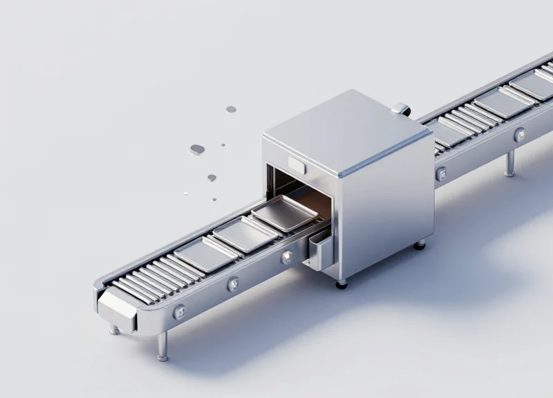
Optimizing for Speed: Tagging in High-Velocity Conveyor Systems

High-velocity RFID tagging involves optimizing the "Time-in-Field" (TiF)—the duration a tag remains within the antenna's effective RF footprint—to ensure the EPC Gen2 "Query-Response" handshake completes before the tag exits the zone. In automated sorting systems moving at speeds of 300 to 600 feet per minute (fpm), engineers must minimize the "Tari" (Type A Reference Interval) and utilize high-gain, circular-polarized antennas to maximize the probability of a successful read within a millisecond window.
| Conveyor Velocity | Time-in-Field (2ft Zone) | Required Reader Strategy |
|---|---|---|
| 200 fpm | 600 ms | Standard High-Gain Linear |
| 400 fpm | 300 ms | Dual-Antenna Cross-Polarized |
| 600+ fpm | <200 ms | Triggered Tunnel with Tari Optimization |
Expert Insight: A common pitfall in high-speed logistics is relying on the default "Session 0" inventory setting. In high-velocity environments, I recommend switching to "Session 1." This ensures that if a tag momentarily loses power due to signal nulls while moving at speed, it immediately becomes available for re-interrogation rather than remaining in a "quiet" state. Furthermore, reducing the Tari value to 6.25 microseconds (the shortest interval permitted by the Gen2 standard) effectively compresses the communication window. This allows the reader to perform significantly more inventory rounds per second, providing the "10ms Rule" buffer needed for the tag to energize and backscatter its payload during rapid transit.
- Calculate Dwell Time: Measure the physical length of the RF read zone and divide it by the maximum belt speed to determine the total millisecond window available for communication.
- Deploy High-Sensitivity Silicon: Utilize tags equipped with high-sensitivity chips like the Impinj Monza R6-P or NXP UCODE 9, which require significantly less power to wake up, shortening the distance needed for activation.
- Antenna Phasing and Geometry: Implement a "tunnel" antenna configuration using four antennas (top, bottom, and both sides) to create a dense, overlapping RF curtain that eliminates orientation-based blind spots.
- Optimize Middleware Latency: Configure the reader's edge software to use low-latency filtering, ensuring that read events are pushed to the WMS or PLC immediately for real-time divert-gate execution.
Does conveyor belt material impact high-speed read rates?
Yes. Metallic belts or rollers reflect RF energy, creating destructive interference nulls. For high-velocity systems, use RF-friendly materials like PVC or modular plastic to ensure signal consistency.
What is the 'Dead Zone' risk at high speeds?
If a tag passes through a destructive interference point (null zone) while moving fast, it may not have enough time to re-energize before leaving the read field. Spatial diversity via multi-antenna arrays is the primary mitigation strategy.
Can Doppler shift affect UHF RFID at extreme speeds?
While Doppler shift is rarely an issue for standard conveyors, at speeds exceeding 1,000 fpm, frequency shifting can theoretically occur. However, the wide bandwidth of UHF channels typically absorbs this variance without data loss.
Security and Encryption in Real-Time RFID Streams
Securing real-time RFID streams involves the implementation of cryptographic protocols at the edge and in transit to protect against data interception, tag cloning, and unauthorized tracking. Because RFID signals are broadcast over the air, data integrity and privacy depend on a 'Security-by-Design' architecture that utilizes Advanced Encryption Standard (AES) for data payloads and mutual authentication protocols (such as those defined in ISO/IEC 29167) to ensure only authorized readers can interact with sensitive tag memory.
| Security Layer | Threat Mitigated | Technical Implementation |
|---|---|---|
| Air Interface Security | Eavesdropping & Skimming | Dynamic session keys and per-packet encryption. |
| Tag Authentication | Counterfeiting & Cloning | Cryptographic handshakes (ECC or AES-128) on-chip. |
| Data-in-Transit | Man-in-the-Middle (MITM) | TLS 1.3 or IPsec tunnels between Reader and Middleware. |
| Integrity Verification | Data Tampering | Hashing algorithms (SHA-256) for audit trails. |
A critical technical challenge in high-velocity supply chains is the 'Security-Performance Paradox.' Adding heavy encryption increases the 'time-on-wire' for each tag read, which can reduce the effective throughput of conveyor systems. To optimize this, engineers should implement Elliptic Curve Cryptography (ECC) for key exchange due to its smaller key sizes and lower computational overhead compared to RSA, ensuring that high-speed sorting remains fluid without compromising the cryptographic envelope.
- Establish a Hardware Root of Trust: Utilize Secure Elements (SE) or Trusted Execution Environments (TEE) within the RFID reader to store master keys, preventing physical extraction by unauthorized personnel.
- Implement Mutual Authentication: Require the tag and reader to prove their identity to each other before sensitive memory banks (like the User Memory or TID) are unlocked for reading.
- Rotate Session Keys: Avoid using static encryption keys. Use a Key Management System (KMS) to rotate keys frequently, limiting the impact of a potential key compromise.
Expert Tip: To achieve maximum security with zero impact on latency, consider using tags with Physically Unclonable Functions (PUF). A PUF acts as a 'silicon fingerprint' created by tiny, random variations in the manufacturing process. Unlike stored keys, a PUF cannot be copied or extracted because the key only exists when the chip is powered on, providing a virtually unhackable identity for every single item in your supply chain.
Can encrypted RFID tags be read as quickly as standard tags?
Modern cryptographic tags using optimized AES-128 engines can complete authentication in milliseconds, though it may slightly reduce the maximum tag-count-per-second in ultra-high-density environments.
Does Gen2v2 support native encryption?
Yes, the EPC Gen2v2 standard introduces enhanced security features, including untraceability and authenticated communication, specifically designed for secure supply chain applications.
What is the biggest risk to RFID security today?
Insecure middleware. While the air interface is often hardened, the connection between the reader and the ERP system is frequently the weakest link if not protected by robust TLS encryption.
Measuring Success: KPIs for RFID Supply Chain Integration
To accurately measure the success of an RFID supply chain integration, organizations must track a bifurcated set of Key Performance Indicators (KPIs): Technical Performance Metrics, which validate the hardware and middleware reliability, and Business Outcome Metrics, which quantify the impact on the bottom line. Success is defined by achieving a First-pass Read Rate (FPRR) of 99.9% while simultaneously reducing labor-intensive inventory counts and shrinking the order-to-ship cycle time.
| KPI Category | Metric Name | Target Benchmark | Primary Goal |
|---|---|---|---|
| Technical | First-pass Read Rate (FPRR) | 99.5% - 99.9% | Validate hardware placement and tuning. |
| Technical | Tag Failure Rate | < 0.01% | Assess tag durability and vendor quality. |
| Business | Inventory Accuracy | > 98% | Reduce out-of-stocks and overstocking. |
| Business | Shrinkage Reduction | 15% - 25% improvement | Identify and eliminate loss points. |
| Systemic | Edge-to-ERP Latency | < 500ms | Ensure real-time visibility for decision making. |
- Inventory Velocity: Measures the speed at which items move through the warehouse. Successful RFID integration typically yields a 10-15% increase in throughput by removing manual scanning bottlenecks.
- Order Cycle Time: The duration from order placement to shipping. RFID minimizes picking errors and automates verification, significantly lowering this metric.
- Read Zone Reliability: Tracking the consistency of reads at specific portals or transition points to identify environmental interference or hardware degradation over time.
Expert Tip: Move beyond simple accuracy and start measuring 'Tag-to-Truth Latency' (TTL). This unique metric tracks the time delta between a physical movement and its digital representation in your WMS. In high-velocity environments, a high TTL—even with 100% accuracy—can cause 'ghost inventory' where the system believes an item is available for sale when it is still physically in transit between zones. Aim for sub-second TTL to enable true synchronous commerce.
What is the most important technical KPI for RFID?
The First-pass Read Rate (FPRR) is the most critical technical metric. It indicates how many tags are successfully read on the first attempt without requiring manual intervention or reprocessing.
How long does it take to see a positive ROI on RFID integration?
Most enterprises see a return on investment within 12 to 18 months, primarily driven by labor savings, reduced stockouts, and improved asset utilization.
Can RFID help with sustainability KPIs?
Yes, by optimizing inventory levels and reducing overproduction and waste, RFID directly contributes to corporate sustainability goals and carbon footprint reduction.