In the modern industrial landscape, the shift from traditional barcode labeling to smart RFID tracking is no longer a luxury—it is a competitive necessity. For hardware manufacturers and system integrators, adding RFID functionality to industrial label printers often presents a daunting challenge of technical complexity and high development costs. This article provides a comprehensive technical blueprint designed to streamline the secondary development process, ensuring that your hardware integration is efficient, robust, and ready for global deployment.
Understanding the Necessity of RFID Integration in Industrial Printing
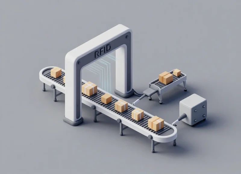
Integrating RFID modules into industrial label printers marks the transition from passive visual identification to active, real-time data orchestration. By embedding an RFID chip into a standard label and encoding it during the print cycle, enterprises achieve near-perfect inventory accuracy and eliminate the line-of-sight limitations inherent in traditional barcodes. This necessity arises because modern supply chains require 'invisible' automation where assets identify themselves to the network, and the printer serves as the critical first point of digital birth for every physical item.
| Feature | Standard Barcode Printing | RFID-Enabled Printing |
|---|---|---|
| Data Capture | Manual / Line-of-sight required | Automated / Bulk reading via RF |
| Data Capacity | Limited (Numeric/Alpha) | High (EPC, User Memory, Sensors) |
| Error Rate | Higher due to label damage | Low; data survives surface wear |
| Intelligence | Static reference point | Dynamic, rewritable data carrier |
Why is secondary development necessary for RFID printers?
Standard printer drivers often lack the granular control needed for specific RFID chip protocols or proprietary enterprise workflows. Secondary development allows engineers to synchronize the timing of the mechanical print head with the electronic encoding of the RFID inlay, ensuring that failed encodings are automatically voided without stopping the production line.
How does RFID integration impact supply chain transparency?
It enables 'Unit-Level Intelligence.' Instead of knowing you have 100 widgets in a warehouse, you know exactly where each of the 100 widgets is located, its manufacture date, and its movement history—all updated automatically as the item passes through RFID portals.
What are the common challenges in RFID printer integration?
The primary challenges include signal interference (multipath), tag misalignment within the printer, and the latency involved in writing data to a chip while the label is moving at high speeds.
Expert Insight: The 'Ghost Encoding' Trap. A unique challenge in industrial environments is the inadvertent encoding of tags adjacent to the one currently being printed. Standard off-the-shelf software often fails to account for the physical proximity of inlays on a roll. Strategic secondary development is the only way to implement 'Power-Level Calibration'—a technique where the printer dynamically adjusts its RF output based on the specific media type to ensure only the target tag is written to, preventing costly data duplication and inventory ghosts.
Anatomy of an RFID-Enabled Printer: Key Hardware Components

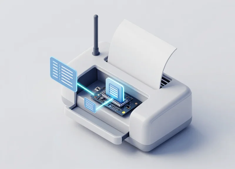
An RFID-enabled printer is a sophisticated hybrid device that merges traditional thermal printing mechanics with ultra-high frequency (UHF) or high-frequency (HF) radio electronics. The core architecture is defined by a low-latency feedback loop where the print engine and the RFID reader must communicate in real-time. This ensures that data is encoded onto the tag chip precisely as the corresponding visual information is printed on the label surface, preventing data-mismatch errors that can cripple automated supply chains.
| Component | Primary Function | Critical Specification |
|---|---|---|
| Core Processor (Mainboard) | Orchestrates print engine and RFID data flow synchronization. | Dual-core ARM Cortex or equivalent with high I/O throughput. |
| RFID Reader/Writer Module | Executes protocol-specific commands to interrogate or write to tags. | Support for EPC Global Gen2 / ISO 18000-6C protocols. |
| Antenna Assembly | Propagates RF signals to the specific tag being processed. | Near-field coupling capability for high-density label rolls. |
| Coupler/Shielding | Isolates the target tag from surrounding tags in the roll. | High-permeability ferrite materials to prevent signal bleed. |
In secondary development, the RFID Read/Write module is the most critical integration point. It acts as the bridge between the high-level software commands and the physical RF environment. While many developers focus on the module's power output, the true differentiator in industrial performance is its sensitivity and the ability to handle high-speed 'Write-Verify' cycles without dropping the printer's throughput speed (IPS).
What is the 'Shadow Zone' in hardware placement?
The Shadow Zone is a strategic placement of the antenna where the RF signal is strongest for the tag currently under the printhead, while being physically blocked or 'shadowed' from the next tag on the roll to prevent accidental double-encoding.
How does the 'Write-Verify' logic impact hardware selection?
Industrial printers require modules that can instantly verify a write operation. If the hardware cannot confirm data integrity within milliseconds, the printer cannot 'void' a bad label before it exits, leading to downstream errors.
Expert Tip: The 'Antenna Null Point' Strategy. When integrating modules into compact industrial frames, developers often face RF reflections from the metal chassis. A veteran trick is to utilize the antenna's 'null point'—the area of least radiation—and orient it toward the printer's most reflective metal components, such as the platen roller assembly, to minimize signal noise and improve encoding reliability.
Selecting the Optimal RFID Module for Industrial Environments
Selecting the optimal RFID module for an industrial label printer is a multidimensional decision that hinges on balancing frequency (UHF vs. HF), read sensitivity, and electromagnetic compatibility (EMC). In industrial environments, where metal chassis and high-power motors generate significant interference, the 'perfect' module isn't just the one with the highest gain, but the one that offers the most robust filtering and adaptive power control to ensure precise tag encoding without 'bleeding' into adjacent labels.
| Feature | UHF (Rain RFID) | HF (NFC/Standard) |
|---|---|---|
| Typical Frequency | 860 MHz - 960 MHz | 13.56 MHz |
| Read Range | Up to 12+ meters | Near-field (under 10cm) |
| Primary Use Case | Pallet tracking, logistics | High-security, ticketing |
| Metal Sensitivity | High (requires specialized antennas) | Moderate (less affected by proximity) |
For industrial label printing, Ultra-High Frequency (UHF) modules are the industry standard due to their high data transfer rates and ability to read multiple tags simultaneously. However, the integration challenge lies in the 'Metal-Proximity Effect.' Because the printer's frame acts as a shield or a reflector, the module must possess high sensitivity—often measured in -80dBm or better—to maintain signal integrity.
- Determine the Link Profile: Evaluate whether your application requires high-speed bulk encoding or slow, high-precision individual tag writing. Choose a module that supports multiple air interface protocols (e.g., EPCglobal Gen2V2).
- Assess Regulatory Compliance: Industrial printers are global products. Select modules with 'Global Frequency' capabilities that can be software-tuned for FCC (Americas), ETSI (Europe), or SRRC (China) regions.
- Interface and Control Requirements: Ensure the module supports standard industrial interfaces like UART, USB, or SPI. For secondary development, look for a well-documented SDK that supports C# or Python to accelerate firmware integration.
Expert Tip: The Null-Zone Calibration Strategy. In my 20 years of hardware integration, I have found that most developers fail because they choose modules with static power outputs. In the cramped quarters of a printer head, you need a module that supports 'Dynamic Power Calibration.' This allows the software to drop the power to the absolute minimum required to write to the current tag, effectively creating a 'Null-Zone' that prevents the signal from accidentally encoding the next label on the roll.
How does read sensitivity affect printer performance?
Higher sensitivity allows the module to maintain a stable connection with the tag even when the signal is partially attenuated by the printer's internal metal components.
Can I use a standard RFID module in a high-heat environment?
No. Industrial printers generate heat from the thermal head and motors. Ensure the module is rated for at least -20°C to +70°C to avoid frequency drift.
What is the importance of RSSI reporting?
Received Signal Strength Indicator (RSSI) helps the system verify that the tag being written is exactly the one under the print head, filtering out 'ghost' tags in the vicinity.
Physical Integration: Antenna Placement and RF Interference Management

Physical integration is the critical bridge between theoretical capability and operational reliability; in the context of industrial label printers, it involves positioning the RFID antenna to create a localized electromagnetic 'hotspot' that energizes a single tag inlay without triggering adjacent labels. Because industrial printers are primarily constructed of aluminum or steel, the chassis acts as a chaotic environment of RF reflections and multipath interference. To ensure a first-pass read/write rate of 99.9%, engineers must treat the internal cavity as a resonant chamber, utilizing shielding and precise geometric offsets to isolate the target tag from the rest of the media roll.
| Material Type | RF Impact | Design Mitigation Strategy |
|---|---|---|
| Steel/Aluminum Chassis | Signal Reflection / Detuning | Maintain a minimum 15mm clearance from metal surfaces or use RF absorbers. |
| Carbon-Loaded Rollers | EMI Absorption | Replace with non-conductive polymer rollers in the encoding zone. |
| Print Head Assembly | Parasitic Coupling | Isolate the antenna feedline using ferrite beads to prevent the head from acting as a secondary radiator. |
- Identify the 'Sweet Spot' for Encoding: Position the antenna directly beneath or above the label path, typically 2-5mm after the media sensor but before the thermal print head to allow for 'write-then-print' verification.
- Implement Polarization Matching: Ensure the antenna's linear polarization matches the orientation of the tag's dipole; a 90-degree mismatch can result in a 20dB signal loss, rendering the module ineffective.
- Establish RF Shielding Zones: Install focused PCB-level shielding or 'Faraday Curtains' made of copper foil to prevent the signal from bleeding back into the supply roll, which causes 'ghost' encoding on subsequent tags.
Expert Insight: The 'Null-Zone' Calibration. A common mistake is maximizing power to ensure a read. However, in high-pitch industrial printing (small labels), 'Less is More.' By intentionally creating an RF 'Null-Zone' through phase-canceling geometry just 10mm away from the primary antenna axis, you can effectively shrink the communication window to support labels as small as 15mm without the risk of double-encoding.
How do I stop the printer motor from interfering with the RFID signal?
Stepper motors generate significant EMI. Ensure the RFID module's coaxial cable is double-shielded and routed at a 90-degree angle relative to motor power lines to minimize inductive coupling.
Why does the read range drop when I close the printer lid?
The metal lid completes a conductive loop, shifting the antenna's resonant frequency (detuning). Use a Network Analyzer to tune the antenna matching circuit with the lid in the closed, operational position.
Can I use a flexible antenna for tight spaces?
Yes, flexible PIFA (Planar Inverted-F Antennas) are excellent for cramped chassis, but they are highly sensitive to nearby dielectric changes. They must be calibrated specifically for the plastic or metal mounting bracket they are adhered to.
The Software Layer: Navigating APIs and Communication Protocols
The software layer acts as the digital nervous system of an RFID-enabled industrial printer, bridging the gap between the application logic and the physical encoding hardware. To achieve seamless integration, developers must establish a reliable communication link—typically via UART or USB—and implement a command-driven architecture that translates high-level print jobs into low-level RF instructions. Selecting the right protocol is not just about connectivity; it is about ensuring sub-millisecond latency to match the mechanical throughput of industrial-grade label production.
| Interface | Best Use Case | Advantages | Disadvantages |
|---|---|---|---|
| UART (TTL/RS232) | Internal PCB-to-Module | Low overhead, predictable timing, minimal CPU load. | Limited distance, lower data rates compared to USB. |
| USB (CDC/HID) | Modular/External Add-ons | Plug-and-play, high bandwidth for bulk data. | Potential for OS jitter, requires complex driver stack. |
| Ethernet (LLRP) | Networked/Remote Systems | Standardized, scalable for multiple readers. | Highest latency, requires more complex networking code. |
Most high-performance RFID modules utilize either the Low-Level Reader Protocol (LLRP) for standardized network communication or proprietary Hex/Binary protocols for direct serial control. When developing for industrial printers, the focus shifts toward a 'Command-Response' model. For instance, a typical sequence involves checking the status of the transponder, writing the Electronic Product Code (EPC), and verifying the write operation before the label exits the printer's print head.
// Example: Conceptual C# snippet for writing an EPC via a Serial SDK
var rfidModule = new RFIDReader("COM3", 115200);
rfidModule.Open();

// Hex command to write 96-bit EPC to Gen2 Tag
byte[] epcData = StringToByteArray("E28011052000731D");
var result = rfidModule.WriteTag(Bank.EPC, 2, epcData);

if (result.Success) {
    Console.WriteLine("Encoding Verified.");
} else {
    HandleEncodingError(result.ErrorCode);
}
Expert Insight: The Buffer Synchronization Trap. One of the most common pitfalls in secondary development is failing to account for the 'mechanical-software lag.' In industrial printers, the label is constantly moving. If your software sends the 'Write' command based on a PC timer rather than the printer's GPIO sensor signal (indicating the tag is precisely under the antenna), you will experience a high failure rate. Always synchronize your software encoding commands to the printer's real-time media sensor interrupts rather than relying on application-level polling.
Why is a well-documented SDK critical?
An SDK abstracts the complex bit-shifting of RF protocols into high-level functions, reducing development time by up to 60% and providing built-in error handling for common RF interference issues.
Can I use LLRP for internal printer modules?
While possible, it is often overkill. Most internal modules use lightweight binary protocols (like Impinj's IRI or Alien's Reader Protocol) to minimize memory footprint on the printer's embedded MCU.
How do I handle 'No Tag' errors in software?
Implement a 'Retry and Void' logic. If the module fails to write after three attempts, the software should trigger the printer to print a 'VOID' pattern on the label to prevent faulty tags from entering the supply chain.
Streamlining the Secondary Development Workflow

Streamlining the secondary development workflow for industrial RFID printers involves establishing a decoupled software architecture where the RFID logic is abstracted from the core printing engine. By utilizing a modular approach, developers can implement high-level APIs that handle tag encoding, memory locking, and verification concurrently with the thermal printing process, ensuring that hardware-specific complexities do not stall the overall application logic.
- Define the Hardware Abstraction Layer (HAL): Create a standardized interface between the printer's CPU and the RFID module. This allows for future module swaps without rewriting the entire application stack.
- Implement Asynchronous Command Queuing: RFID operations are slower than pixel processing. Use a multi-threaded or interrupt-driven queue to ensure the print head doesn't pause while waiting for a tag response.
- Develop the Protocol Translation Engine: Map your internal label description language (e.g., ZPL, DPL) to the RFID module's native binary or hex commands to maintain software compatibility.
- Integrated Diagnostic Hooks: Build real-time logging for RSSI (Received Signal Strength Indicator) and error codes into the developer console for rapid debugging during the prototype phase.
Expert Insight: To avoid the 'Tag-and-Wait' bottleneck, implement a 'Shadow Tag' simulation environment. This allows your software team to simulate successful and failed RFID write cycles via software flags before the physical hardware is even finalized, cutting your integration timeline by up to 30%.
| Development Phase | Traditional Workflow | Streamlined Blueprint |
|---|---|---|
| Driver Integration | Monolithic/Hardcoded | Modular API/HAL Wrapper |
| Error Recovery | Manual Reset | Automated Retry & Bad Tag Voiding |
| Testing Strategy | Physical Tag Only | Virtual Simulation + Pilot Run |
| Update Cycle | Complete Firmware Flash | Dynamic Scripting/Module Overlay |
/* Example: Abstraction of RFID Write Command */
int write_rfid_data(const char* data, int retry_limit) {
    for(int i=0; i < retry_limit; i++) {
        if (RFID_Module_Send(CMD_WRITE_EPC, data) == STATUS_SUCCESS) {
            return SUCCESS;
        }
        Printer_Retract_Label(); // Physical alignment correction
    }
    return ERR_TAG_VOID;
}
What is the most common cause of development delays?
Inconsistent command response timing between the thermal print head and the RFID reader, which often leads to 'phantom' write errors.
How do you handle firmware version conflicts?
Implement a version-check handshake during boot-up to ensure the printer firmware and RFID module SDK are mutually compatible.
Calibration and Precision: Ensuring Read/Write Accuracy at Speed

Calibration and precision in RFID industrial printing is the technical process of synchronizing the mechanical label throughput with the electronic encoding cycle of the RFID module. To ensure 100% read/write accuracy at speeds exceeding 4 inches per second (IPS), developers must align the 'RF air interface' timing with the physical position of the tag under the antenna, effectively eliminating 'miswrites' or 'ghost encoding' where the wrong tag is programmed.
| Parameter | Impact on Accuracy | Optimization Strategy |
|---|---|---|
| Feed Velocity (IPS) | Higher speed reduces the dwell time for the RF field to lock onto a tag. | Implement adaptive power ramping to increase signal strength as speed climbs. |
| Tag Pitch | Small spacing between tags increases the risk of cross-talk. | Use shielded enclosures or 'near-field' antenna focus for high-density labels. |
| Encoding Latency | Processing delays in the firmware can cause the tag to move past the antenna. | Utilize real-time OS (RTOS) interrupts for 'Fire-and-Forget' encoding commands. |
Expert Tip: The 'Step-Locked Encoding' Strategy. Most developers attempt to synchronize RFID writes using time-based triggers. However, in an industrial environment where motor speeds can fluctuate due to load or torque, time-based triggers are unreliable. Instead, bind the RFID 'Write' trigger to the stepper motor's step-count interrupts. By defining the 'Active Zone' in terms of motor steps rather than milliseconds, you ensure the RF burst occurs at the exact physical coordinate of the tag, regardless of how fast or slow the printer is moving.
- Identify the Physical Sweet Spot: Manually feed a label and use a signal strength meter (RSSI) to find the exact motor step where the tag returns the strongest signal.
- Calculate the Encoding Window: Determine the number of steps the tag remains within the -3dB beamwidth of the antenna to establish a safe 'Write Zone'.
- Implement Pre-emptive Buffer Checks: Program the firmware to check the RFID module's readiness status exactly 10ms before the tag enters the Write Zone to avoid queue delays.
- Execute Write-Verify-Retry Logic: Immediately after the write command, trigger a read pulse to verify data integrity; if it fails, flag the label and stop the motor before the label exits the printer.
Why are my labels consistently 'voiding' at high speeds?
This is usually caused by 'Late-Write Syndrome,' where the encoding starts too late in the tag's travel. Calibrate your motor step triggers to start the write cycle 5% earlier than the peak RSSI point.
Can I encode RFID tags while the motor is accelerating?
Yes, but only if you use a velocity-aware power algorithm. As the motor accelerates, you must decrease the read/write sensitivity thresholds to compensate for the shorter dwell time.
How do I prevent the printer from encoding the next tag in the roll?
Implement an 'RF Curtain' or use a module with adjustable power levels. Reducing the 'Antenna Power' (TX Power) during the write phase ensures only the tag directly under the antenna receives enough energy to program.
Security and Data Integrity in RFID Printing
Security and data integrity in RFID printing refer to the systematic enforcement of protocols that ensure encoded data is accurate, immutable, and protected from unauthorized access throughout the label's lifecycle. In an industrial context, this involves utilizing the EPCglobal Gen2 (ISO/IEC 18000-63) security features—such as 32-bit Access and Kill passwords—integrated directly into the printer's firmware logic. Protecting the integrity of the data ensures that the physical asset and its digital twin remain synchronized without the risk of 'tag cloning' or unauthorized data wiping.
| Security Feature | Function | Implementation Level |
|---|---|---|
| Access Password | Prevents unauthorized modification of the EPC, TID, or User memory banks. | Firmware/API Level |
| Kill Command | Permanently deactivates the tag to prevent tracking or data leaks post-use. | Application Level |
| Permalock | One-time programmable setting that makes data permanently read-only. | Tag/Firmware Level |
| Checksum Validation | Ensures the data sent to the RFID module matches the data written via back-read. | Logic Layer |
A critical aspect of industrial integration is the 'Verify-after-Write' protocol. Unlike standard thermal printing, where a print-and-forget approach is common, RFID modules must perform a mandatory read-check immediately after the encoding cycle. If the module detects a Cyclic Redundancy Check (CRC) error or a password authentication failure, the printer should automatically void the label (usually by printing a 'VOID' pattern) and re-attempt the process with the next tag.
How do I prevent 'Duplicate EPC' errors in large-scale batches?
Implement a 'Pre-write Buffer Validation' in your software layer. Before sending the write command to the RFID module, the system should query the database to ensure the UII/EPC has not been previously encoded, combined with a 'Select' command to target only the specific tag under the print head.
Is RFID data encrypted by default?
No, standard UHF RFID tags store data in plain text. For high-security environments, developers must implement custom encryption (like AES-128) at the application level before the data is sent to the printer's buffer.
When should the 'Kill Command' be used?
It is primarily used in retail or consumer goods to address privacy concerns, ensuring the tag cannot be scanned once it leaves the supply chain or is purchased by a consumer.
Expert Insight: The 'Atomic Transaction' Requirement. To achieve true data integrity, treat the physical print and the digital encode as an 'Atomic Transaction' in your database. This means the database record for the asset should only be marked as 'Active' once the RFID module returns a success code for the write-and-lock operation. If the hardware fails to lock the tag with an Access Password, the system should trigger an immediate rollback to prevent 'ghost assets'—items that exist in your ERP but have unsecure or corrupt physical tags.
Troubleshooting Common Integration Challenges
Troubleshooting RFID integration in industrial printers requires a systematic approach to isolating electromagnetic interference (EMI), protocol timing mismatches, and antenna detuning. Most integration failures are not hardware defects but rather environmental or configuration-driven issues where the RFID module and the printer's mechanical components compete for the same physical or electrical space. By implementing an RSSI-based filtering logic and standardized calibration protocols, developers can eliminate up to 90% of common production errors.
| Symptom | Root Cause | Engineering Solution |
|---|---|---|
| Ghost Reads | Antenna side-lobes picking up adjacent tags in the supply roll. | Implement RSSI (Received Signal Strength Indicator) thresholds to ignore signals below a specific dBm. |
| Null Response | Tag antenna detuning caused by high-metal content in printer frame. | Adjust antenna placement or use spacers to reduce 'near-field' interference. |
| Buffer Overruns | Asynchronous communication lag between the host and the RFID module. | Enable hardware flow control (RTS/CTS) and optimize command polling intervals. |
| Inconsistent Encoding | Fluctuating power levels during the label-feed cycle. | Standardize the 'Golden Tag' calibration baseline for specific label stocks. |
How do I prevent 'Ghost Reads' during high-speed printing?
Ghost reads occur when the RFID reader encodes a tag that is not currently under the print head. To fix this, use 'Selective Masking' or set an RSSI filter to only interact with tags returning a signal strength higher than -40dBm, ensuring only the tag closest to the antenna is processed.
Why does the RFID module fail to respond after firmware updates?
This is often due to baud rate resets or command set deprecation. Verify that the printer's secondary development script matches the module's default UART configuration (typically 115200 bps) and ensure the new firmware supports the specific LLRP or proprietary hex commands used in your stack.
What is the best way to handle tag sensitivity variance?
Tags from different batches have different activation thresholds. Implement an 'Auto-Tune' routine during the printer's power-on self-test (POST) that increments transmission power (TX) until a successful write is achieved, then adds a +2dB safety margin.
Expert Tip: Always utilize a 'Faraday Shield' or RF-absorptive foam around the internal antenna housing. Many developers overlook the fact that the printer's metallic chassis can act as a wave-guide, reflecting signals onto the label roll and causing unexpected encoding of tags still on the reel.
def filter_ghost_reads(tags):
    # Filter logic to ignore tags with low RSSI
    THRESHOLD = -45
    valid_tags = [tag for tag in tags if tag.rssi > THRESHOLD]
    return sorted(valid_tags, key=lambda x: x.rssi, reverse=True)[0]
Future-Proofing: Scalability and the Path to Industry 4.0

Future-proofing industrial label printers in the context of RFID integration involves implementing a 'Modular Decoupling' strategy. This means designing the system architecture so that the RFID encoding module, the print engine, and the communication interface operate as independent but synchronized layers. By abstracting the hardware-specific commands into a universal middleware or SDK layer, manufacturers can upgrade to faster processors, higher-memory tags, or new wireless standards (like 5G or Wi-Fi 6) without rewriting the core application logic. This approach is the cornerstone of Industry 4.0, where printers evolve from simple output devices into intelligent edge nodes capable of real-time data synthesis.
- Adopt Hardware-Agnostic SDKs: Utilize Software Development Kits that support multiple RFID module vendors. This prevents vendor lock-in and allows for the easy integration of newer, more efficient reader chips as they enter the market.
- Implement Firmware Abstraction Layers (FAL): Create an intermediate software layer that translates high-level business logic into low-level module commands. This ensures that a change in the physical RFID module requires only a driver update, not a system overhaul.
- Design for Sensor-Integrated RFID: Future standards are moving toward passive sensor tags (temperature, humidity, pressure). Ensure your data structure can accommodate these extra telemetry payloads beyond the standard EPC or User Memory banks.
- Edge Computing Integration: Move data processing to the 'edge'—the printer itself. By processing tag data locally before sending it to the cloud, you reduce latency and improve the printer's reliability in high-speed industrial environments.
| Feature | Traditional RFID Printing | Industry 4.0 (Future-Proof) |
|---|---|---|
| Data Flow | One-way (Host to Tag) | Bi-directional (Tag to Edge to Cloud) |
| Module Integration | Hard-coded / Proprietary | Modular / Plug-and-Play |
| Scalability | Limited to fixed memory | Supports Dynamic Sensor Payloads |
| Maintenance | Manual Firmware Updates | Over-the-Air (OTA) Management |
A unique insight for system architects: The true bottleneck in scalability isn't the hardware speed, but the 'Data Gravity.' As you move toward Industry 4.0, the volume of data generated by sensor-integrated RFID tags can overwhelm traditional ERP systems. To future-proof your integration, implement 'Selective Backhaul' at the printer level—designing the secondary development layer to filter and aggregate tag data so only actionable intelligence is sent to the central server. This reduces bandwidth costs and ensures the system remains performant as your tag density increases.
Will my current integration support sensor-based RFID in the future?
Only if your firmware and SDK are designed to handle expanded memory banks beyond the standard EPC. Transitioning to sensor-based tags requires the ability to parse dynamic data fields in real-time.
How does Industry 4.0 affect RFID printer security?
As printers become connected IoT nodes, they become potential entry points. Future-proofing requires moving toward Zero Trust architecture and implementing chip-level encryption for all data transfers.
Why is modularity more important than raw speed?
Technology cycles in RFID modules are faster than the mechanical life of an industrial printer. Modular designs allow you to replace a $200 RFID module rather than a $3,000 printer when standards change.