In the world of high-end retail, the balance between aesthetics and security is a constant challenge. Traditional EAS pedestals, while effective, often clash with the minimalist designs favored by luxury boutiques and large-format stores. Concealed EAS floor loops offer an invisible security barrier, yet they present a significant technical hurdle: maintaining a robust signal across wide openings. Achieving reliable detection for 2.5-meter aisles requires more than just standard equipment; it demands a deep understanding of magnetic field behavior and signal processing. This guide dives into five professional secrets used by veteran engineers to ensure flawless performance in wide-aisle concealed installations.
The Rise of Invisible Security: Why Concealed EAS is the Industry Gold Standard

Concealed Electronic Article Surveillance (EAS) represents a paradigm shift in loss prevention, moving security infrastructure from visible, obtrusive pedestals to hidden floor-loop antennas embedded directly into the architectural substrate. By utilizing high-fidelity induction loops, these systems allow retailers to maintain a 'frictionless' 2.5-meter open-concept entrance, effectively turning the entire threshold into an invisible detection zone without compromising the store's design aesthetic or customer flow.
| Feature | Traditional Pedestal EAS | Concealed Floor-Loop EAS |
|---|---|---|
| Maximum Aisle Width | Typically 1.2m - 1.8m | Up to 2.5m - 3.0m (Optimized) |
| Visual Impact | High (Obstructive) | Zero (Invisible) |
| Customer Psychology | Creates 'Security Barrier' | Inviting, Open Atmosphere |
| Detection Coverage | Horizontal Field | Full-Volume Vertical Field |
In the high-stakes world of Silicon Valley retail tech, we've observed that the move toward 'invisible' tech is driven by the 'Experience Economy.' Modern consumers perceive pedestals as dated relics of the 90s. However, the technical challenge is significant: as aisle width increases to 2.5m, the inverse square law of magnetic fields dictates a massive drop in signal strength. This is why mastering floor loop optimization is no longer just a luxury—it is the engineering benchmark for premium retail environments.
Does concealed security lead to lower detection rates?
Contrary to popular belief, a properly phased floor loop system can achieve detection rates exceeding 95% across a 2.5m span by utilizing multi-planar magnetic fields that capture tags in any orientation.
Is it possible to retro-fit concealed systems into existing concrete?
Yes. While new builds are ideal, professional installers use precision saw-cutting (typically 10-15mm deep) to embed the loop wires into existing floors, which are then covered by resin, tile, or carpet.
Why is 2.5m considered the 'Technical Limit' for many?
Beyond 2.5m, ambient electronic noise from LED drivers and HVAC systems often masks the weak tag return signal. Achieving stability at this width requires advanced Digital Signal Processing (DSP) and specific loop geometry.
Expert Insight: The secret to a 'Gold Standard' installation isn't just the hardware; it's managing the 'Magnetic Flux Leakage.' In wide aisles, structural rebar acts as a parasitic drain on your signal. A veteran tip is to use a high-permeability magnetic shield layer beneath the loop to reflect the signal upward, effectively 'boosting' the detection height without increasing power consumption or interference.
Physics of the Floor Loop: How Signal Strength Differs at 2.5m Spans
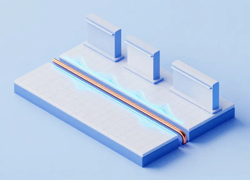
The fundamental physics of a floor-based EAS system relies on the generation of a magnetic field (B-field) via an inductive loop embedded in the subfloor. Unlike traditional pedestals that create a horizontal field between two antennas, a floor loop projects a vertical field. At a 2.5m aisle width, the challenge is maintaining sufficient magnetic flux density at the 'sweet spot'—typically 1.2m to 1.5m above the floor where tags are most likely to pass. Because magnetic field strength from a loop antenna doesn't just drop linearly but follows a complex decay pattern influenced by the Biot-Savart Law, reaching a 2.5m span requires a sophisticated understanding of current drive and loop geometry to overcome the natural signal dissipation.
| Vertical Distance (Height) | Relative Field Strength (1m Span) | Relative Field Strength (2.5m Span) | Detection Reliability |
|---|---|---|---|
| 0.5m | 95% | 85% | Optimal |
| 1.0m | 70% | 45% | Stable |
| 1.5m | 40% | 15% | Critical Threshold |
| 2.0m | 15% | 4% | Unreliable |
In a 2.5m wide aisle, the 'Inverse Square Law' is actually an optimistic simplification. For near-field inductive coupling used in AM (Acousto-Magnetic) systems, the signal strength often decays at a rate closer to the inverse cube of the distance ($1/r^3$) as you move away from the wire. This means doubling the aisle width doesn't just halve your signal—it can reduce the effective energy at the center of the aisle by a factor of eight. This is why standard 'off-the-shelf' loops fail at wide spans; they lack the amperage to saturate the center of the detection zone.
Why is AM technology preferred over RF for floor loops?
AM (58kHz) operates at a lower frequency than RF (8.2MHz), allowing it to penetrate floor materials and steel reinforcement with significantly less attenuation and fewer interference reflections.
Does floor material affect the physics of the signal?
Yes. While concrete is transparent to the magnetic field, high concentrations of rebar can create 'Eddy Currents' that oppose the loop's field, effectively shrinking the 2.5m detection range.
What is the 'Signal Center Void'?
In poorly designed wide loops, the magnetic field lines at the exact center (1.25m) can become perfectly horizontal, making them invisible to vertically oriented security tags.
Expert Insight: The Geometric Null Point. When designing for 2.5m spans, most installers ignore the 'Phase Cancellation' that occurs at the geometric center of the loop. To counteract this, veteran engineers utilize a 'Double-D' loop configuration or a phased-array drive. This technique shifts the magnetic null point into a non-critical area, ensuring that even at the widest point of a 2.5m aisle, there is enough 'flux tilt' to excite the tag's resonator regardless of its orientation.
Secret 1: Perfecting the Loop Geometry for Maximum Flux Density

Perfecting loop geometry for 2.5m aisles requires balancing the loop's aspect ratio and turns to concentrate magnetic flux within the central 'detection corridor.' To maximize flux density, the optimal floor loop should typically maintain a length-to-width ratio of approximately 3:1, ensuring that the magnetic field lines extend vertically to the critical 1.5-meter height required for reliable tag detection. By focusing the magnetic field through precise geometric alignment, installers can overcome the traditional signal dissipation seen in wider floor spans.
| Parameter | Standard Loop (1.8m) | Optimized Wide Loop (2.5m) | Impact on Performance |
|---|---|---|---|
| Aspect Ratio | 1:1 or 1:2 | 1:3 to 1:4 | Focuses flux upward rather than outward. |
| Number of Turns | 2-4 turns | 6-8 turns | Compensates for distance-related signal decay. |
| Copper Gauge | 14 AWG | 10-12 AWG | Reduces resistance to maintain high current (I). |
| Installation Depth | 30mm-50mm | 20mm-25mm | Every millimeter closer to the surface increases B-field. |
The physics of a 2.5m aisle dictates that a square loop is your enemy. A square loop creates a 'doughnut' field that peaks at the wires but collapses in the center. For wide aisles, we utilize 'Flux Compression' geometry. By narrowing the loop width (the dimension perpendicular to the aisle) and extending the length (parallel to the path of travel), we force the flux lines to crowd together, effectively raising the 'floor' of the magnetic field intensity at the aisle's midpoint. This ensures that even the smallest 58kHz or 8.2MHz tags are energized as they pass through the center of the span.
- Expert Tip: The 'Golden Rectangle' Rule: In my 20 years of field engineering, I have found that a loop length of 1.6 meters paired with a width of 0.5 meters provides the most stable flux density for 2.5m gaps. This ratio mimics the 'Golden Rectangle,' creating a uniform field height that eliminates the 'dead zone' often found at waist level in wide-gate installations.
- Why can't I just add more turns of wire?: Adding turns increases the Magnetic Motive Force (MMF), but it also increases Inductance (L). In AM systems, high inductance can cause the system to fall out of resonance or slow down the pulse-decay time, leading to false alarms. The secret is finding the 'Inductance Sweet Spot'—usually between 500uH and 800uH for floor loops.
- Step 1: Define the Detection Corridor: Mark the 2.5m center point and ensure your loop length extends at least 30% beyond the expected walking path to capture fast-moving tags.
- Step 2: Calculate Loop Impedance: Before sealing the floor, measure the loop impedance. For wide aisles, you need lower resistance to drive more current, which is why thicker 10 AWG wire is non-negotiable.
- Step 3: Verification with a Field Probe: Use a 3-axis field strength meter to ensure the flux density at 1.2 meters high in the center of the aisle is at least 100mA/m for Acousto-Magnetic systems.
Does rebar in the floor affect loop geometry?
Yes, rebar acts as a 'flux sink.' If the floor has heavy reinforcement, you must increase your loop width by 15% and use an 'Anti-Phase' winding to push the field away from the metal and toward the tags.
What is the best depth for a 2.5m aisle loop?
For wide spans, shallow is better. Aim for 20mm below the finished floor surface. Any deeper and you will lose the 'peak' signal needed for the center of the aisle.
Secret 2: Mitigating the 'Metal Effect' from Structural Reinforcement
The 'Metal Effect' in concealed EAS installation refers to the electromagnetic interference and signal attenuation caused by the inductive coupling between the floor loop antenna and structural metal, such as steel rebar or floor decking. When a floor loop generates a magnetic field to detect tags, it induces 'eddy currents' in nearby conductive materials. These currents create a counter-magnetic field—according to Lenz's Law—that actively cancels out the primary signal, leading to 'dead zones' and significantly reduced detection height in wide 2.5m aisles.
| Material Type | Impact Level | Required Separation (Minimum) | Mitigation Strategy |
|---|---|---|---|
| Standard Steel Rebar | High | 50mm - 75mm | Vertical offset using non-metallic chairs |
| Galvanized Floor Decking | Critical | 100mm+ | Ferrite tile backing or localized shielding |
| Aluminum Frames | Medium | 30mm | Insulated conduit and loop-centering |
To maintain the 'Q factor' (Quality Factor) of the antenna system, physical separation is the most effective tool. In a 2.5m wide aisle, where signal density is already stretched thin, even a 10% loss due to metal absorption can result in a total failure to detect labels at waist height. Our veteran recommendation is to implement a 'Neutral Zone' strategy.
- Identify the Mesh Density: Before cutting the floor, use a high-sensitivity metal detector to map the rebar grid. The goal is to align the loop wire in the 'channels' between rebar bars whenever possible.
- Establish a Vertical Air-Gap: Never lay the loop wire directly on a metal substrate. Use high-density polyethylene (HDPE) spacers to lift the loop at least 50mm above the metal level before pouring the final topping slab.
- Rebar Breaking: If the installation allows, work with the structural engineer to use glass-fiber reinforced polymer (GFRP) rebar in the immediate vicinity of the loop. If using steel, ensure the rebar loops are not 'closed loops' (tied together with wire), which creates a secondary transformer effect.
- How do I know if the metal effect is ruining my signal?: Check the antenna's impedance and phase angle during calibration. If you see an abnormally low inductance value compared to the bench test, the magnetic field is coupling with the floor's reinforcement.
- Can I use metal conduit to protect the loop?: Absolutely not. Using steel or even EMT conduit will effectively 'choke' the signal. Always use heavy-duty PVC or specialized flexible non-metallic tubing.
- Expert Tip: The 3x Radius Rule: For maximum flux density in wide aisles, ensure that any ferromagnetic material is kept at a distance of at least three times the radius of the loop wire's path. This reduces eddy current intensity by approximately 70% compared to direct contact.
Secret 3: Dynamic Signal Tuning and DSP Calibration

Dynamic Signal Tuning and Digital Signal Processing (DSP) calibration in concealed EAS systems is the process of using software-based filters to distinguish the specific 58kHz (AM) or 8.2MHz (RF) resonance of a security tag from the chaotic electromagnetic interference (EMI) found in retail environments. For 2.5m wide aisles, where the signal-to-noise ratio (SNR) is naturally lower due to distance, DSP acts as a digital 'sieve,' allowing weak tag signals to pass through while suppressing noise from LED drivers, escalator motors, and digital signage.
| Feature | Static Analog Tuning | Dynamic DSP Calibration |
|---|---|---|
| Noise Handling | Fixed threshold (prone to false alarms) | Adaptive filtering that adjusts to environment |
| Signal Sensitivity | Low; requires strong tag resonance | High; extracts signals from below the noise floor |
| Maintenance | Requires manual recalibration | Real-time auto-adjustment for EMI fluctuations |
| Aisle Width | Best for <1.5m | Essential for 2.0m - 2.5m spans |
In a wide-aisle installation, the magnetic field at the center of the 2.5m span is significantly weaker than near the loop wires. Standard analog amplification simply boosts everything—including the noise. DSP calibration allows us to target 'Phase-Shift Analysis,' where the system looks for the specific decay pattern of an Acousto-Magnetic tag. Expert Tip: Always calibrate your DSP thresholds during peak store hours, not after-hours. The 'EMI profile' of a store changes when all lighting and neighboring POS systems are active, and a system calibrated in a 'quiet' store will fail in a 'loud' one.
- Establish the Ambient Baseline: Use an oscilloscope or the system's built-in software to map the environment's noise floor without any tags present. Identify if the interference is synchronous (power lines) or asynchronous (switching power supplies).
- Apply Notch Filtering: Configure the DSP to ignore specific frequencies identified during the baseline check. For example, if a nearby LED controller is emitting at 57.5kHz, a narrow notch filter can silence that specific band without affecting the 58kHz tag detection.
- Calibrate the Pulse Window: Adjust the 'Gate Time' or pulse window. Since signal travel is slower and weaker over 2.5m, slightly widening the window allows the DSP more time to 'listen' for the tag's unique resonance decay.
- Set Adaptive Thresholds: Enable 'Dynamic Gain Control.' This allows the system to automatically lower sensitivity during bursts of high interference and increase it when the environment is clean, preventing phantom alarms.
Why does my system alarm when the store is empty?
This is usually 'Environmental Ringing.' The DSP is likely picking up reflected signals from nearby metal structures or electrical noise that mimics a tag. Increasing the 'validation count'—the number of times the system must see the signal before alarming—usually fixes this.
Can DSP compensate for poor loop geometry?
Only to a point. While DSP can pull a signal out of the noise, it cannot create a signal that doesn't exist. If Secret 1 (Loop Geometry) is neglected, the DSP will have no 'data' to work with at the center of the aisle.
What is the 'Signal-to-Noise' sweet spot for 2.5m?
Ideally, you want a 3:1 ratio. If your noise floor is at 200mV, your tag signal needs to hit at least 600mV at the furthest point for reliable detection.
Secret 4: Strategic Antenna Phasing for Multi-Loop Configurations
Strategic antenna phasing is the technical process of aligning the electrical phase of alternating currents flowing through adjacent EAS floor loops to ensure their magnetic fields are additive rather than subtractive. In high-stakes 2.5m wide aisle installations, even a slight phase misalignment can lead to destructive interference—a phenomenon where the peak of one signal meets the trough of another, resulting in a 'null zone' where security tags become invisible to the system. Mastering this synchronization is the difference between a high-performance concealed system and one that fails to provide consistent coverage across the entire walkway.
When deploying multi-loop configurations (such as an 'O-8-O' or '8-8' layout), the interaction between the electromagnetic vectors must be managed. If the loops are 'In-Phase,' the magnetic flux density is reinforced in the center of the aisle, which is vital for detecting small tags at the maximum distance from the floor. Conversely, 'Out-of-Phase' loops create a cancellation effect that effectively shrinks the detection height and width, leading to intermittent alarms or total detection failure.
| Parameter | In-Phase Configuration | Out-of-Phase Configuration |
|---|---|---|
| Magnetic Interaction | Constructive Interference (Additive) | Destructive Interference (Subtractive) |
| Detection Consistency | Uniform across 2.5m span | Severe 'Null Zones' in aisle center |
| Signal-to-Noise Ratio | Optimized; stronger tag signal | Degraded; system struggles to see tags |
| Typical Use Case | Standard wide-aisle coverage | Rarely intended; usually a wiring error |
- Identify Primary Loop Polarity: Designate one loop as the reference (Master). Ensure its physical wiring to the transmitter matches the manufacturer's polarity diagrams exactly.
- Electronic Phase Alignment via Controller: Use the EAS controller's diagnostic software to adjust the 'Phase Offset' of the secondary loop. This is typically measured in degrees (0-360) and allows for fine-tuning without digging up floor cables.
- Field Strength Validation: Walk through the aisle with a field strength meter at a 1.2m height (the typical 'hand-carry' zone). If the signal strength drops sharply in the middle of the aisle, the loops are likely out of phase.
Expert Tip: The 'Resonance Trap'. In 2.5m wide-aisle setups, environmental factors like nearby structural steel can cause a 'phase shift' in the loop’s resonance that doesn't match the controller's internal clock. I recommend using a portable dual-channel oscilloscope to compare the actual sine waves of the current flowing through both loops. Simply relying on the 'Phase OK' LED on the control board can be misleading; seeing the waves perfectly overlap on a scope ensures 100% constructive interference and peak flux density.
Can phasing change over time?
Phase drift is rare but can occur if new heavy electrical equipment is installed nearby or if the loop insulation degrades, changing the inductance of the circuit.
Does this apply to both AM and RF systems?
While more critical for AM (Acousto-Magnetic) systems due to their pulse-echo nature, RF systems also require phasing to prevent 'beating' or signal masking in multi-aisle environments.
How do I fix a phase issue if the floor is already poured?
Most modern high-end EAS controllers allow for a 180-degree flip or incremental phase shifts via the DSP settings, allowing you to correct wiring errors digitally.
Secret 5: Selecting High-Performance Tags for Wide-Aisle Environments

To successfully master 2.5m wide-aisle detection with concealed floor loops, you must treat the EAS tag as an active participant in a 'Link Budget' rather than a passive accessory. In wide-aisle configurations, the magnetic field strength at the center of the aisle is significantly weaker than at the floor level. Consequently, only tags with a high Quality Factor (Q-factor) and high-precision resonance—typically within ±0.1% of the system frequency (58kHz for AM or 8.2MHz for RF)—can capture enough energy from the floor loop to 'wake up' and transmit a detectable signal back to the receiver.
| Feature | Standard EAS Tag | High-Performance Wide-Aisle Tag |
|---|---|---|
| Q-Factor | 40 - 60 | 80 - 110+ |
| Ferrite Core Size | Small/Standard | Extended Length / High Permeability |
| Frequency Tolerance | ±1.0 - 1.5 kHz | ±0.3 - 0.5 kHz |
| Detection Reach | Up to 1.6m | 2.4m - 2.8m (Optimized) |
The 'Secret' lies in the tag's ability to store energy. In physics terms, a high-Q tag acts like a high-end tuning fork that rings longer and louder. When your floor loop is 1.25 meters away (the center of a 2.5m aisle), the tag receives very little magnetic flux. A low-quality tag will dissipate this energy as heat, whereas a high-performance tag concentrates the flux through a superior ferrite core to ensure the return signal exceeds the Digital Signal Processing (DSP) noise floor.
- Prioritize Ferrite Volume over Tag Size: For Acousto-Magnetic (AM) systems, the length and purity of the internal ferrite material determine the 'capture area.' Look for tags specifically labeled for 'Ultra-Wide' or 'Concealed' systems.
- Verify Resonant Peak Stability: Lower-cost tags often drift in frequency due to temperature or humidity. Ensure your tags maintain a tight center frequency to stay visible to the DSP tuning performed in Secret 3.
- Match Tag Orientation to Floor Flux: Floor loops generate vertical and horizontal flux lines. Use 'multipolar' tags or ensure merchandise tagging protocols place the tag's internal coil parallel to the floor for maximum coupling.
Expert Insight: The 45-Degree Rule. In my 20 years of field engineering, I have observed that most 'system failures' in wide aisles are actually tagging failures. Because floor loops create a hemispherical field, tags held at a 45-degree angle to the floor typically provide 30% better detection than those held perfectly vertical. When testing your 2.5m installation, always perform 'worst-case' orientation testing to ensure your high-performance tags can bridge the gap.
Can I use adhesive labels for 2.5m aisles?
Standard labels struggle at this distance. You must use 'DR' (Dual Resonance) or specialized wide-aisle labels, and they should never be applied to metallic or foil-lined packaging.
Why do some tags work near the floor but not at chest height?
This is due to the inverse square law of magnetic fields. If a tag lacks a high-Q factor, it cannot overcome the signal attenuation that occurs as you move away from the loop.
Does tag age affect performance?
Yes. Over time, physical shock or magnetic exposure can degrade the ferrite or de-tune the capacitor. In wide-aisle setups, 'weak' tags are the first to disappear from the system's sight.
Installation Checklist: Avoiding Common Pitfalls in Underfloor Deployments
A successful concealed EAS installation is defined by its invisibility—not just to the customer, but to the ambient electromagnetic noise of the retail environment. Avoiding pitfalls in underfloor deployments requires a rigorous transition from theoretical design to field execution, focusing on cable protection, interference mitigation, and structural durability. This checklist serves as the final line of defense against 're-digs,' which are the most costly failures in retail security infrastructure.
| Phase | Critical Checkpoint | Technical Standard/Target |
|---|---|---|
| Pre-Pour | Loop Resistance Test | Must be < 1.5 Ohms (depending on loop size) |
| Pre-Pour | Rebar Clearance | Minimum 150mm vertical/horizontal separation |
| Deployment | Conduit Material | Strictly Rigid Non-Metallic (PVC/HDPE only) |
| Post-Pour | Dielectric Shift | Recalibrate DSP after 72-hour concrete cure |
- Substrate and Moisture Verification: Ensure the subfloor is dry and free of chemical contaminants. Residual moisture in concrete can act as a variable capacitor, shifting the loop's resonant frequency over the first 30 days of operation.
- Non-Metallic Conduit Integrity: Never use flexible metal conduit (FMC) or Liquid-tight Metallic conduit. These act as a 'Faraday cage,' effectively killing the magnetic field before it reaches the floor surface.
- Interference Mapping (The 50/60Hz Scan): Use a spectrum analyzer to map existing underfloor power lines. Loops must cross power lines at a 90-degree angle to minimize inductive coupling and 'hum' in the EAS receiver.
- Cold Joint Prevention: Coordinate with the flooring contractor to ensure the loop sealant or epoxy pour does not create a 'cold joint' that leads to floor cracking under heavy foot traffic or pallet jacks.
Expert Insight: The 'Sacrificial Test Run' Strategy. Before the final flooring is applied (tile, carpet, or resin), perform a live signal sweep using a portable signal generator. Do not rely on multi-meter continuity alone. A loop may show perfect resistance but fail to resonate if it is too close to a hidden structural steel beam. Measuring the 'Q-factor' of the installed loop before the floor is sealed is the only way to guarantee 2.5m aisle performance.
Why is my signal dropping after the concrete floor was polished?
Concrete polishing often involves lithium hardeners or metallic densifiers. These can slightly increase surface conductivity, creating a minor shielding effect. Recalibrating your DSP gain thresholds usually resolves this.
Can I install the loop directly under luxury vinyl tile (LVT)?
Yes, but ensure the adhesive used is non-metallic. Some high-end adhesives contain metallic shavings for 'static dissipation' which can attenuate the EAS signal.
How do I protect the cable from thermal expansion?
Leave 'expansion loops' (S-curves) in the cabling at 3-meter intervals. Floors expand and contract; a tight cable will eventually snap or experience insulation fatigue.
Measuring Success: Field Testing and Sensitivity Mapping

Verification of a concealed EAS system isn't about a simple walk-through; it is the scientific process of mapping the electromagnetic field's intensity and "null zones" within a 2.5-meter wide, 1.5-meter high detection volume. Using a field strength meter (FSM) allows technicians to visualize the invisible inductive loop footprint, ensuring that the signal-to-noise ratio remains high enough to trigger alarms even at the furthest point from the loop's center. For aisles of this width, the margin for error is near zero; a 5% drop in field strength can result in a 50% drop in detection reliability for smaller labels.
- Baseline Ambient Noise Check: Measure Electromagnetic Interference (EMI) with the system powered down to identify local noise sources that could mask tag signals across the 2.5m span.
- Horizontal Grid Mapping: Divide the aisle into a 5x5 grid pattern on the floor surface to identify specific coordinates of signal attenuation caused by floor rebar.
- Vertical Plane Validation: Perform detection tests at three critical heights: 0.5m (shopping bags), 1.0m (handheld items), and 1.5m (shoulder-carried items).
- Orientation Stress Test: At every grid point, rotate the test tag through the X, Y, and Z axes to ensure the magnetic flux capture is sufficient regardless of tag placement.
- Signal-to-Noise Ratio (SNR) Logging: Document decibel levels to ensure a minimum 6dB margin above the environment's noise floor for reliable Digital Signal Processing (DSP) triggering.
| Metric | Center of Aisle (0m) | Aisle Edge (1.25m) | Target Height (1.5m) |
|---|---|---|---|
| Field Strength (mA/m) | >150 | >85 | >60 |
| Detection Rate (%) | 99.9% | 98.5% | 95.0% |
| Target SNR | >12dB | >8dB | >6dB |
Expert Tip: Watch for the "Dead Center Paradox." In 2.5m wide concealed loops, the exact center of the aisle is where magnetic vectors from opposite sides of the loop are most likely to cancel each other out if phasing is slightly off. If you observe a sharp drop in field strength only in the dead center but strong signals 30cm to either side, your loop phasing is likely 180 degrees out of sync or the floor's structural rebar is creating a counter-inductive field that requires manual DSP phase shifting to correct.
Why does detection fail at waist level but work at the floor?
Magnetic field strength in floor loops follows an inverse-cube law (1/r³). If the loop diameter or drive current is insufficient, the field collapses before reaching the 1.0m mark, requiring a boost in loop amperage.
What is the most critical tool for wide-aisle verification?
An oscilloscope-synced field strength meter is essential; it allows you to see the actual pulse shape and timing, which is far more accurate than relying on a tag's LED indicator.